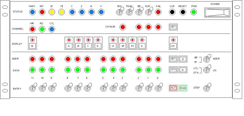
Detailed descriptionThe Console is composed by four panels. From top to bottom, those panels are:
* Status
* Channel Selection
* Display Source
* Data and Execution Control
Status Panel
The WAIT lamp illuminates when a WAIT signal is present in any of the 16 channels.
The INT lamp monitors all 16 Interrupt signals feeding the Interrupt Controller circuit. The lamp remains illuminated as long as one interrupt signal at least is present. This is true even if interrupts are disabled by either software or hardware.
The IE lamp monitors the Interrupt Enable flag. It illuminates if interrupts are enabled by software. Similarly, the TE lamps indicates whether Trap is enable.
Lamps C, Z, N, V monitor the flags: Carry, Zero, Negative, Overflow (respectively) from the flag register.
The IRQ (Interrupts Request) switch, when inactive (down), prevents the Interrupt signals from reaching the Interrupt circuit causing the CPU to ignore all interrupts even if those are enabled by software. The Interrupt Enabled (IE) flag is not affected by this switch.
The TRAP switch enables/disables "traps". When a fail condition occurs, if trap is enable by software and the TRAP switch is active (up), a trap routine is called automatically.
The BP (Halt on Break Point) switch, when active (up), causes the computer to halt when the program counter reaches a certain address previously set by the operator. We cover this later in this section.
Lamp FAIL illuminates when the CPU recognizes a Fail condition and remains in that state until the operator clears the condition explicitly by pressing the CLR button.
The HOF (Halt On Fail) switch, when active (up), causes the CPU to halt as soon as a fail condition occurs. This is useful for debugging.
The RESET button fires the Master Reset signal causing all CPU registers to clear up. The signal is also spread throughout all I/O channels to clear peripheral circuitry as well.
PWD lamp indicates that the Power Supply is on. The Power switch turns the Power Supply on or off.
Channel Selection Panel
The four CH NUM (Channel Number) lamps indicate in binary what channel is currently selected. This reading changes dynamically during program execution as different channels are selected by software.
When the computer is halted, the Operator can select the channel manually. This is done by entering the channel number in binary using the four least significant Entry Switches, then pressing the SET button near the CH NUM lamps.
Lamps WR, RD illuminate when the selected channel is being written or read, respectively.
As mentioned in section "I/O Architecture", peripherals are expected to have two internal registers exposed to the channel: DATA and CONTROL. The lamp CTL illuminates when the peripheral's CONTROL register is being read or written
Display Source Panel
Buttons in this panel allow to select the source for the DATA 12-lamps Display in the Data and Execution Control panel. Only one source is selected at the time, which is indicated in the lamp mounted in the corresponding button.
Button M selects "Memory". When selected, the DATA display shows memory content. The next eight buttons select registers: A, B, C, D, IX, SP, PC and S respectively to be shown in the DATA display. The CH button selects Channel.
During normal program execution, the Operator can operate these buttons to read memory, registers or channel content dynamically.
Data and Execution Control Panel
The two 12-lamps displays ADDR and DATA read from Memory or registers depending of the selection made in section Display Source Panel.
When reading from Memory, the DATA display reads the memory location which address is shown in display ADDR. If the computer is halted, the Operator can set this address by entering its value in the Entry Switches, then pressing the SET button near the ADDR display. As soon as the button is pressed, both ADDR and DATA displays change to reflect that address and its memory content.
The address can be also incremented or decremented by pressing buttons ">" or "<" respectively. Once the button is preset, both displays are automatically updated.
When a register or channel is selected (instead of M) in the Display Source panel, the ADDR display continues to show memory addresses, either in halt or normal program execution modes.
Button STO (store) allows to over-write content to either memory, register or channel (as selected in the Display Source section). When pressed, the content in the Entry Switches are copied to the selected register, the selected channel, or the memory cell which address is currently in the ADDR display.
Button HTL (halt) halts the machine. The button illuminated to indicate such condition.
Button RUN cause the machine to enter normal program execution mode. Program starts from the address currently stored in the Program Counter register. The button illuminates to indicate such condition.
Buttons SET, <, >, STO are disabled automatically during normal program execution.
Single-Step Execution
If the STEP switch is in its active position (up), the computer will halt after completing the next instruction cycle. Pressing the RUN button repeatedly allows to run the program one instruction at the time.
To resume running the program normally, down the STEP switch, then press the RUN button.
If the switch is soddenly activated (up) during normal program execution, the computer will halt once the current instruction cycle is completed, entering single-step execution mode.
Break Point
A Break Point is a memory address set by the Operator so when the program reaches it, the machine halts automatically. This is useful for debugging.
If the switch BP (Halt on Break Point) is active (up) in the Status panel, program execution will stop as soon as the Program Counter reaches the break point; the instruction at that address will not be executed. Pressing the RUN button again will resume program execution, but if the same address is reached again, the machine will halt again. If you place a break point in the middle of a loop, for example, you will be able to execute the loop one iteration at the time.
The switch "BP/M" allows the operator to select what the ADDR display is actually reading; that could be either Break Point (up) or Memory (down). When in the BP position, pressing the SET button causes the Entry Switches content to be set as the "Break Point" address.
During normal program execution, the Operator can operate the BP/M switch to dynamically change the ADDR display reading between Break Point and memory address.
|