ContentThis section covers the operation of the Master Controller (MC) and the other different units that comprises the LC-81 minicomputer.
Master Controller Console
The Console provides the very first mean for operating the LC-81 minicomputer. Using the Console, the operator can start and stop a program from given address, examine and modify memory and I/O content, allow or disallow Interrupt and DMA requests from peripherals and to monitor several CPU status signals.
Worth to mention, the Console operates based on hardwired logic independently from the microprocessor (that is, without software assistance) except for the START button functionality which utilizes a little program (seven bytes of machine code) contained into the MC EPROM.
Anatomy
The Console is composed by two panels.
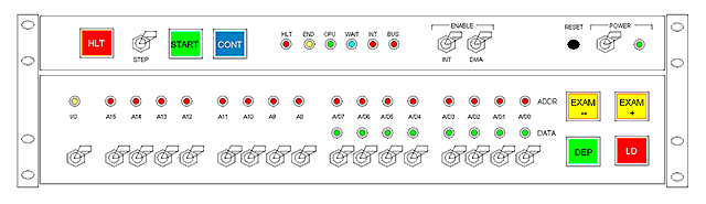
The top panel contains the HLT, START, CONT and RESET buttons, the STEP, INT, DMA and POWER switches and different status Lamps. Using these controls, the operator defines the operational mode of the machine.
The bottom panel provides the (17-Lamps) Address Display, the (8-Lamps) Data Display and the (17) Entry Switches as well as EXAM-, EXAM+, LOAD and DEPOSIT buttons. Using this panel, the operator can examine and modify content into either memory or I/O as well as to define the starting address for program execution.
Operational Modes
The LC-81 minicomputer operates in two distinct modes: Halt and Run.
Right after power on or reset the computer falls automatically into Halt Mode. No initialization software runs at this time. Once in Halt Mode, the Console can be used for examining or changing memory or I/O content.
Pressing the START or CONT button causes the machine to enter Run Mode.
Once in Run Mode, the Entry Switches and the EXAM-, EXAM+, LD, DEP buttons becomes inoperative. The Lamps Displays keep showing the current memory or I/O being accessed by the program. This is the mode in which software actually runs.
Pressing the HLT or RESET button causes the machine to enter Halt Mode again.
Examining memory or I/O content
The Address and Data displays are always in sync, that is, the Data Display shows the content of the memory location or I/O register which address is currently shown by the Address Display. If it is a memory address, the I/O Lamp will be off. If it is an I/O address, the I/O Lamp will illuminate and only the first eight bits of the Address Display will be valid (since I/O addresses are 8-bits).
Pressing the EXAM- or EXAM+ button causes the Console to read the previous or next address respectively. The new address will be shown in the Address Display and the content for that location will be shown in the Data Display. Whether this is memory or I/O address depends upon the I/O switch status: if it is in active position (up) the address corresponds to I/O; it will be a memory location otherwise.
For examining an arbitrary memory location or I/O, proceed as following: Use the entry switches for entering the desired address then press the LD button. Again, if the I/O switch is in its active position (up) the address entered will be interpreted and an I/O address and only the first eight bits will be valid. Once the LD button has been pressed, the corresponding memory location or I/O will be read so the Data Display will show the content and the Address Display will show the address.
Keying in the Entry Switches will not cause any effect until either the LD or DEP button is pressed. You can, for example, enter a new address as described above then use the EXAM-, EXAM+ buttons to examine consecutive locations and, later on, press the LD button for returning to the initial address, which is still given by the Entry Switches.
Modifying memory or I/O content
Memory or I/O content can be modified one location at the time by using the Entry Switches and the DEP (deposit) button. In order to do that, proceed as following:
Navigate to the desired location as described in previous section. Use the first eight Entry Switches to indicate the desired content (up position for "1", low position for "0"). Press the DEP button.
Pressing the DEP button causes the current location to be written as defined by the first eight Entry Switches. A read cycle on the next memory or I/O location takes place automatically so the Address Display and the Data Display will show the address and content of the next location, not the one you just wrote. This is convenient for writing in a block of memory (for instance, a short program).
Running a Program
You must know the initial address of the program you want to run. It can reside either in EPROM, RAM, private or shared memory. For starting the program, key its initial address in the Entry Switches and press the LD button so you see that address in the Address Display and the first byte of the program in the Data Display. Then press the START button.
Pressing the START button causes the Console to assert a Non Maskable Interrupt (NMI) request to the microprocessor. The short interrupt routine reads the given address into the Program Counter (PC) so execution starts immediately at that address. The computer has entered Run mode.
You can stop the program at any time by pressing the HLT button. This causes the computer to enter Halt mode. No memory nor I/O content gets changed: the computer has simply frozen at this point.
Stopping a program this way is useful for debugging. Once the computer is halted you can use the Console to examine or even change memory or I/O content in order to repair data corruption or program miscoding.
For resuming execution press the CONT button. This will cause the program to continue from exactly the same point in which it was stopped independently of current Display reading or Entry Switches positions.
For restarting execution from a different given point, proceed as you did when started the program, that is, key the desired address, press LD, then START.
A program may terminate with a Halt instruction. This will cause the computer to freeze but not to enter Halt mode. This condition is called "soft halt" and is indicated by the "END" Lamp. In order to escape from soft halt you can either restart the program by pressing the START button or to reset the computer by pressing the RESET button. Production programs are not expected to terminate this way but it might be useful for testing purposes (kind of break point).
Single-Step Execution
The STEP switch is used to run a program one instruction at a time which may result useful for debugging.
If the switch is in active position (up), the computer will fall into Halt mode immediately after having executed the current instruction. Pressing the CONT button will cause the next instruction to execute after which the computer will halt again. You can press the START button instead to branch execution to any different address.
You escape from this condition by flipping the STEP switch to its inactive position (down).
INT and DMA switches
Putting the INT (interrupt) switch to its inactive position (down) causes the EXT-BUS line IRQ (interrupt request) not to reach the intended destination, thus having external interrupts unavailable.
In systems making use of external interrupts, the INT switch must remain active (up) all the time. However, you may want to flip it down for testing purposes.
This also apply to the DMA switch with respect to the EXT-BUS line BRQ (bus request). In systems making use of DMA, this switch must remain in active position (up) all the time except for testing purposes.
Status Lamps
The top panel of the Console features the following status lamps: HLT, END, CPU, WAIT, INT, BUS.
The HLT lamp (Halt) illuminates when the computer is in Halt mode, remaining off otherwise.
The END lamp monitors the microprocessor's signal Halt. This lamp illuminates when a Halt instruction is executed. As mentioned, this makes the microprocessor to stop but not the machine to enter Halt Mode. To actually halt the computer at this time you can press the HLT button in which case you will see both the HLT and the END lamps illuminated.
The CPU lamp monitors the microprocessor's signal M1. Consequently, this lamp illuminates for each time the microprocessor fetches for operational code thus indicating that the CPU is actually running code.
The WAIT lamp monitors the microprocessor's input signal Wait. This signal is used to make the CPU to hold awaiting response from a slow device which had requested such by pulling down the HLD line of the EXT-BUS.
A Wait signal is also asserted internally within the MC circuitry to coordinate DMA operations with external memory or I/O usage throughout the EXT-BUS as explained in section Master Controlller. Consequently, the lamp will also illuminate when an external device is requesting bus usage an the microprocessor has abdicated in favor of the device.
The INT lamp monitors the incoming IRQ signal before the INT switch, indicating that an external device is requesting interrupt to the Master Controller.
The BUS lamp monitors the EXT-BUS signal BSY (Bus Busy). This occurs when the MC is attempting to access the EXT-BUS, that is, trying to address shared memory or I/O.
It must be noticed that this lamp signals, not that the MC is actually using the EXT-BUS but only that it "wants" to do so. For example, if the MC tries to access external memory while a DMA transfer is taking place, you will see both the BUS and the WAIT lamps illuminated as long as the transfer takes. This is because the microprocessor have been put in hold automatically in favor of the DMA transfer (See "EXT-BUS Gating" in section Master Controller).
|