Quick ReferenceThis section summarizes information found in the rest of the Manual, for quick access.
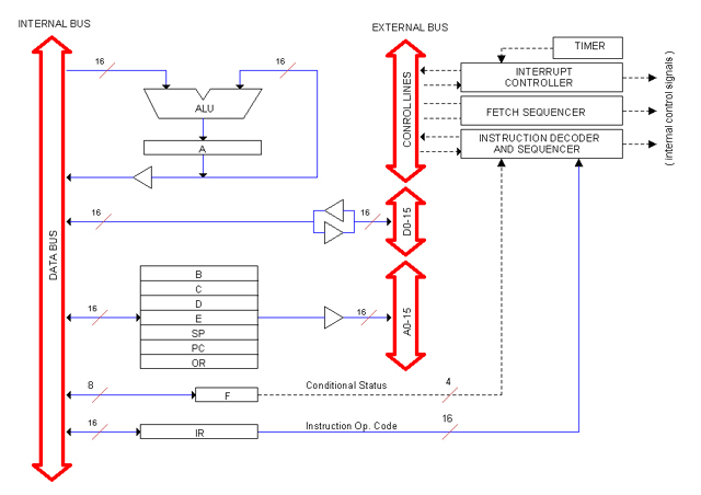
CPU Block Diagram
REGISTERS:
- General Purpose (B, C, D, E)
- Special Purpose (A, PC, SP)
- Hidden (IR, OR, F)
- Console (LAR, LDR, SW)
All of them are 16-bits except F, the Flags register, which is 8-bits.
Control Signal Prefixes
LD_ Load (clock to latch)
OTD_ Output To Data (open buffer to D-BUS)
OTA_ Output To Address (open buffer to A-BUS)
OTL_ Output To Lamps (open buffer to L-BUS, the "lamps" bus)
INC_ Increment
DEC_ Decrement
Board Names
Naming convention:
H1ut-d[-v]
Where:
H1 Denotes Heritage/1 computer
u Unit: 1 for CPU, 2 for Core Unit, etc.
t Type: C for controller, R for register, D for non-register data-oriented board.
d Description: (Board-specific)
v Version (optional)
Example:
H11R-PC-2 (Register PC, located at the CPU, board version 2).
CPU Boards
Board Name Description Location
-------------------------------------------------------------
H11C-INT Interrupt Controller Backplane Slot #1
H11C-BUS Bus Controller Backplane Slot #2
H11D-ALU1 ALU board 1 Backplane Slot #3
H11D-ALU2 ALU board 2 Backplane Slot #4
H11R-A Register A Backplane Slot #5
H11R-LARLDR Console registers (LAR, LDR) Backplane Slot #6
H11R-PC Register PC Backplane Slot #7
H11R-SPOR Registers SP, OR Backplane Slot #8
H11R-GEN Registers B, C Backplane Slot #9
H11R-GEN Register D, E Backplane Slot #10
H11C-MC Master Controller Backplane Slot #11
H11C-IDS1 IDS card 1 Backplane Slot #12
H11C-IDS2 IDS card 2 Backplane Slot #13
[ More IDS cards may exist on slots #14-18 ]
H11D-CONL Console Display Lamps (left) Console assembly
H11D-CONL Console Display Lamps (right) Console assembly
H11D-CONB Console stu Lamps and Buttons Console assembly
H11C-CONC Console Controller Console assembly
Note: Boards with same name are interchangable.
Specifications
|