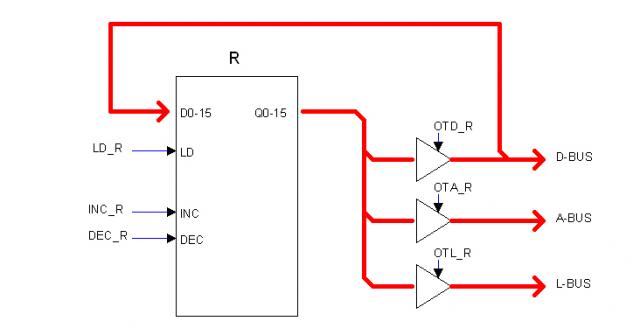
Control SignalsThe figure below represents a typical Heritage/1 register as an example of a circuit being controled by internal control signals.
The circuit encapsulated into the box can latch a 16-bits word. It can also increment or decrement its content. Latched content is always available at the Q0-15 outputs but those are isolated from the buses by the mean of three 3-state buffers as shown.
Control signal LD_R makes the register to latch its inputs D0-15 which are connected directly to the D-BUS. Signals INC_R and DEC_R makes the content to increment or decrement respectively.
In order to expose the register's content to the D-BUS, signal OTD_R must be present. Similarly signal OTA_R makes the content available to the A-BUS and OTL_L, to the L-BUS. This later is the "lamps bus" which content is always shown in the Console's Data Lamps (LEDs).
The naming convention for control signals is: SIGNAL_RESOURCE as in LD_R (Load register R). Common prefixes are (among others):
LD_ Load (clock to latch)
OTD_ Output To Data (open buffer to D-BUS)
OTA_ Output To Address (open buffer to A-BUS)
OTL_ Output To Lamps (open buffer to L-BUS, the "lamps" bus)
INC_ Increment
DEC_ Decrement
All control signals are active low with no exception. This makes it easier to "OR-them" using diodes.
|
Homebuilt CPUs WebRing
JavaScript by Qirien Dhaela
Join the ring?
David Brooks, the designer of the Simplex-III homebrew computer, has founded the Homebuilt CPUs Web Ring. To join, drop David a line, mentioning your page's URL. He will then add it to the list.
You will need to copy this code fragment into your page.
Project start date: May 13 of 2009
|