Console Operation
Anatomy
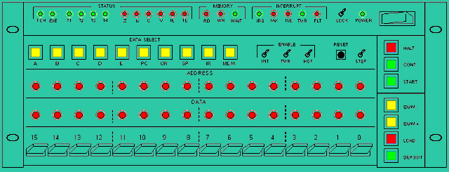
The Console consists of the following sections:
# Entry Section:
The Entry Section allows to enter data directly into memory from the Entry Switches, in binary. This section consists of the sexteen Entry Switches and the buttons: LOAD, DEPOSIT, EXAM+ and EXAM-.
# Address Display (A-DISP):
Sixteen lamps reading from the address bus.
# Data Display (D-DISP):
Sixteen lamps reading from memory or internal registers (selectable).
# Status Display (S-DISP):
Nineteen lamps displaying different status signals such as the flags register content.
# Data Selector (D-SEL):
Ten push buttons for selecting the D-DISP source. This can be memory or any of the CPU internal registers: A, B, C, D, E, PC, SP, OR, IR.
# Machine Control:
These buttons and switch establish the operational mode of the machine. Buttons in this section are: HALT, START, CONT. The switch is: STEP.
# Interrupt Control:
These toggle switches allow to enable or disable the timer (TMR), external interrupts (INT) and to make the computer to halt automatically when a fault condition is reached (HOF).
# Others:
There is also a RESET button and a Panel Lock toggle switch.
For all control switches on the Console, the active position is "up", the inactive position is "down". For instance, you defeat external interrupts by putting the INT switch to its down position.
For Entry Switches, the "up" position is binary one (1), the "down" position is binary zero (0).
All buttons are momentary actuating, meaning that the associated action will take place immediately after pressing the button and won't be affected by how long you keep the button depressed nor by the moment in wish you release it.
Panel Lock
When the LOCK switch is in its active position (up) all other buttons and switches get "locked", with the only exception of the POWER switch and the LOCK switch itself. It is recommended to keep the Console locked during normal operation in order to avoid accidental handlings.
When you unlock the Console, those switches that were already in active position will take action immediately. For instance, if you put the TMR switch up while the Console is locked, the Timer will remain inactive but it will become active as soon as you deactivate the LOCK switch. You must be careful when you unlock the Console making sure that all switches are in the desired position before you do.
Power and Reset
As each unit in Heritage/1 is powered separately, you turn the computer on by actuating power switches on all of the units. It is recommendable to power the CPU first, then the Core Unit, then the others. It is also recommended to put all Console switches to their inactive position before proceeding.
On power-on, an internal reset signal is generated automatically but you can issue a manual reset at any time by pressing the RESET button (if the LOCK switch is in inactive position).
The reset signal brings the computer into a "clean" initial state by clearing all pertinent internal flip-flops. No memory cell, however, nor any of the internal registers will be cleared, with the only exception of the Flags register (F) and the Instruction Register (IR).
After reset, the computer falls automatically into "Halt mode" which is one of the two operational modes possible; the other is "Run mode". While in Halt Mode, Timer and External interrupts remain inactive.
Please notice that no software will run by its own thus reset involves hardware initialization only.
Selecting the D-DISP source
Using the Data Selector buttons you select what to display in the D-DISP. That can be Memory or any of the internal registers: A, B, C, D, E, PC, SP, OR, IR. You can change your selection at any time during program execution or when the computer is in Halt mode.
Immediately after power-on all registers (except F and IR) as well as all memory cells contain nothing but random values. You may want to select "Memory" at this point because it is convenient for entering your star up program.
Entering the start up program
Software (such as the Operating System) is stored on tape; however, in order to read from tape into memory, a "loader" program is needed. You enter that "loader" (or whatever initial software is required) by mean of the Entry Section of the Console.
First, set the starting address as following:
1.- Actuate the Entry Switches to reflect the desired initial address.
2.- Press the LOAD button.
You will see the address reflected in the A-DISP. A memory read cycle will be performed automatically over that address and its content will be displayed in the D-DISP (if "Memory" have been selected in the Data Selector).
Second, enter the memory content as following:
3.- Actuate the Entry Switches to reflect the data word desired for the first location.
4.- Press the DEPOSIT button. The Entry Switches content will be copied into memory. A memory read cycle over the next address will be performed so you will see the A-DISP incremented and the D-DISP displaying the content of that memory cell, must likely the random value it contained after power-on.
5.- You can keep entering data this way. You can also use the EXAM-, EXAM+ buttons to examine content from the previous or next memory cells respectively; A-DISP and D-DISP will get conveniently updated. You can even jump to a different address as in steps 1 and 2. Please notice that when you press the DEPOSIT button, the Entry Switches content is copied into the memory cell which address is the one shown by the A-DISP at that time; hence, if you navigate away from the current "insertion point", you must get back to that point before continuing with data entry.
6.- Bring the A-DISP to reflect the initial address again (as in step 1). Now you can run the program by pressing the START button, as explained in the next section.
Normal Execution
The Machine Control section of the Console allows you to start, stop or continue a program loaded in memory, either in Normal or Step execution mode.
When you press the START button, execution starts at the address currently shown by the A-DISP. This is the normal way to run the starting program you just entered as explained in previous section.
Immediately after pressing the START button, the computer falls into Run Mode meaning that the program is now in full control of the machine. The A-DISP continually shows the memory address being accessed (either by the Program Counter or other register). The D-DISP shows the corresponding content if "Memory" is selected on the Data Selector, or the selected register's content otherwise.
In Run Mode, buttons in the Entry Section get locked. Buttons in the Machine Control Section get locked too with the exception of HALT. You can let the program to run normally or you can stop it by pressing the HALT button after which the machine will fall into Halt Mode after have finished to execute the current instruction.
Step Execution
To run a program is Step Mode, activate the STEP switch (up). In this mode, only one instruction is fetched and executed at a time after which the machine falls into Halt mode automatically. You run the next instruction by pressing the CONT button.
Normally, you stop the machine (by pressing the HALT button) before activating the STEP switch, but you can also activate the switch directly while the computer is still running. In that case, the machine will let the current instruction to finish, then will fall into Halt mode.
Step Mode is useful for debugging developing programs. Say for instance that your program crashes. What you do is to enter Step Mode as explained; for each step (while in Halt mode), you possibly examine different registers and memory contents in order to figure out what the problem is.
As said, you can press the CONT button to execute the next instruction. In that case the program will continue from the point it was left with total independence of the A-DISP reading. This implies that, between steps, you can freely explore the memory by using the Entry Section of the Console; the execution of each step, however, will update A-DISP and D-DISP as it does for normal execution.
You can also run the next instruction from any given point in memory by pressing the START button instead. When you do that, the program counter (PC) is loaded with the content shown by the A-DISP. Thus, in order to execute from a given address, you enter that address in the Entry Switches, press the LOAD button, then the START button.
You can leave Step Mode at any time by putting the STEP switch down again. When you do that, the machine is must likely in Halt mode so you will possibly need to press the START or CONT button to resume normal execution.
Interrupt Control switches
Heritage/1 accepts software interrupts as well as three types of hardware interrupts: Timer, External and Fault.
The Timer Interrupt is generated by the CPU in a timely basis; it has the highest priority and cannot be masked by software. External interrupts are requested by interrupter peripherals via the external bus (U-BUS); there can be up to 65,536 external interrupts and can be disabled or enabled all together by software (instructions EI and DI respectively). The Fault interrupt is generated by different circuits in the CPU capable of detecting fault condition such as invalid instruction code; faults cannot be masked by software. For more details on Interrupts see: Interrupt Architecture in the Engineer's Manual.
The switches in the Interrupt Control section of the Console allows you to handle those interrupts in a privileged way with total independence of software.
The TMR switch must be active (up) for the timer to function. Similarly, external interrupts won't get the CPU attention if the INT switch is not in its active position. The switch Halt-On-Fault (HOF) allows to fall in Halt automatically as soon a fault condition is detected.
It is recommended to start the computer with all of these switches inactive. Once the system is in normal execution, activate TMR and/or INT if your system is making use of those interrupts. The switch HOF is only used for debugging purposes.
Remember that in Halt mode, Timer and External interrupts will be disabled automatically; this is independent from the TMR and/or INT switches positions. When execution is resumed (either in Normal or Step mode) interrupts will be available or not according with the TMR and INT switches positions.
Software interrupts cannot be defeated from the Console.
|