Homebrew Mini-Computer based on Z80 CPU |
armandoacostawong@gmail.com |
-- Sorted in ascendant order (Most recent bottom).
4/4/2011
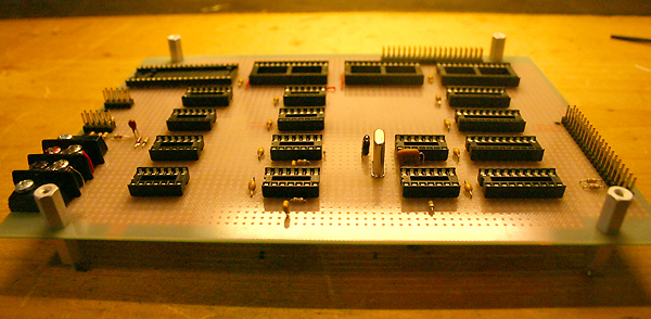
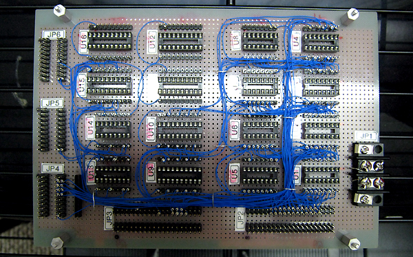
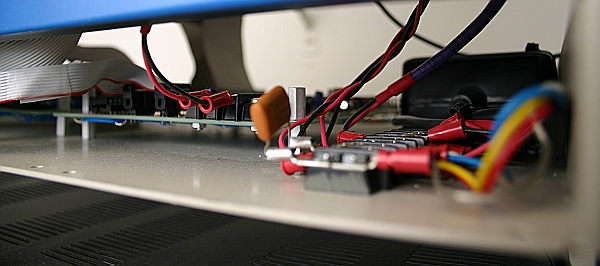
Finished placing and soldering all pasive components on the CPU Board as well as the little "half-moons" that will serve to guide wires into hardness avoiding the "big mess of wires". Also tested the oscilator circuit.
4/14/2011
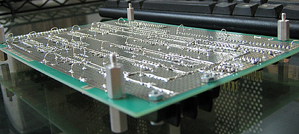
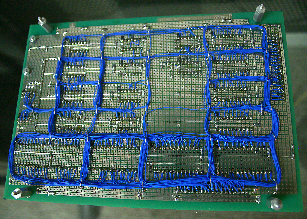
Finished wiring the CPU Board, very late in the night, testing will start tomorrow friday (hopefully). Found a couple of little mistakes in the schematics; to be fixed in revision 9.
It took eight days to wire this single board. Not too fun... I'm seriously considering wire-wrap for the next board: the Console Controller.
4/15/2011
Testing this board took the whole day. I found several mistakes not only in the wiring but also in the schematics. I also did some modifications on the fly. Correct versions have been posted (revision 9).
In principle, it worked, but not entirely correct. I suspect it is because of wiring mistakes that I haven’t found yet, so testing will continue.
4/17/2011
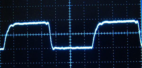
The problem with my clock's waveform was fixed by replacing U13 (a 74ACT04 chip used in the clock generator) with its TTL counterpart 74LS04.
Yet another wiring mistake was found in the Address Bus. Some other minor modifications was made that will be posted in revision 10, shortly.
The circuit does not work yet. It seems that the microprocessor is not following the code written in the EPROM but a "random" code instead.
I suspect a tricky race condition exists behind the unusual way this machine is been halted and started (BUSREQ combined with NMI). Another suspicion is about EPROM response time since I'm employing surplus used (and old) ones.
4/20/2011
After five days of intense work fixing flaws and making minor modifications on the fly, the CPU Board can now run short test programs stored into different EPROMs I've burned. The Step mechanism seems to work too though that will be easier to test when the Console Controller is ready.
Fresh schematics will be posted shortly. I will now take a short vacation. My next task upon return is the Console Controller board.
5/1/2011
The Console Controller ended up bigger than initially thought. I'm employing small prototyping boards so had to split the circuit into two boards called respectively: Console Registers Board and Console Controller Board. The former provides the required "lamps registers" (LAR and LDR) as well as muxes and 3-state buffers. The later produce the control signal sequences needed to operate the Console on the Operator's commands.
I finished the schematic for the Console Registers board but I feel it is going to change soon.
An idea on how to build sequences in the Console Controller board has been also formulated; this is by using a diodes matrix with 14 rows by 14 columns.
6/3/2011
Before starting to build the Console Registers board I want to make sure the Console Controller board will fit well within the current design so I won't start building the first until the last had been designed. But before getting into this I want to finish the Display boards so that is precisely what I'm doing now.
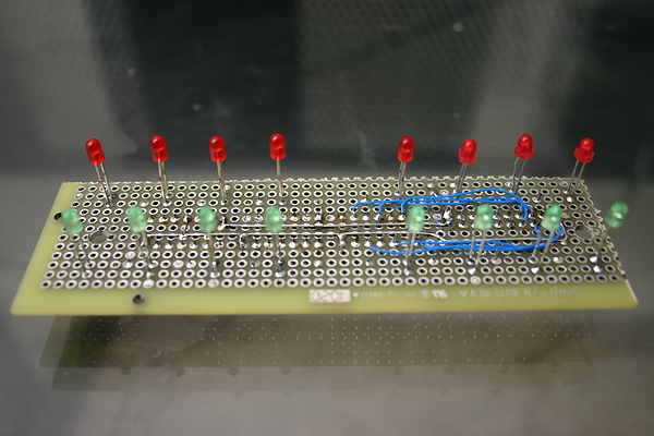
It is quite difficult because of the LED legs standing just in the middle.
6/9/2011
Finished to wire the two Display boards. Next step: designing the Console Controller board.
6/14/2011
I'm still working on the Console Controller design. Not sure if I'll be able to meet the deadline (6/19/2011).
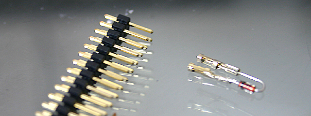
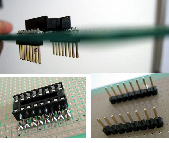
This board is intended to produce sequences such as memory read/write cycles without any software assistance. It operates based on "microcode" implemented with a diodes matrix (about 50 diodes). Yesterday I came with this funny idea to make my diodes "pluggable" so I can fix "microcode" bugs with easy:
6/18/2011
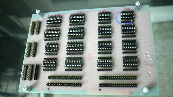
Today I started to build the Console Registers board. I had planned to finish the Console Controller design before starting to built this one, fearing unpredicted changes to be done to this as a result of the design of the other. But now the drawing is almost finished and is it clear that it will not impact the Console Registers board.
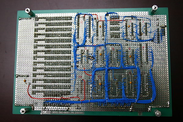
I'm not soldering wires this time. Instead, I'm adopting the low-cost wire-wrapping technique demonstrated in this video by a guy who's name is not revealed, also adopted by Dawin Pilawa in his D.Y.I. Computer Project. Now is my turn for giving it a try.
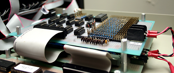
At this moment, the board is in "preparation" phase (the soldering part). The blue wires appearing in the picture are not part of the circuit; it was me exercising a little bit just to have a taste.
6/19/2011
Finished the Console Controller drawing in time according to schedule, and posted to Quick Card. This is revision 1.
Wiring of the Console Registers board continues.
6/25/2011
The "soldering part" is complete. Wire-wrapping has started: It points to become a "big mess of wires"... not too good to me.
6/26/2011
Wire-wrapping of the Console Register board continues at rapid pace based on the low-cost technique learnt from Internet. To be honest... not entirely satisfied with it: mess or wires on the components side don't look nice.
Looking for alternatives (within the low budget still) I came to this funny idea last night, illustrated in the image below. Not to be implemented for now.
7/1/2011 -- The Wiring List
Could not meet my deadline. At least two more work-days will be required to complete the Console Registers board wiring.
So far I've been guiding my self directly from the schematics but today I started to employ a "wiring list" as recommended by John Doran in this document found in his web site: General Notes on Wire-Wrap Construction.
By the way, that is a good reading for those interested in professional wirewrapping.
It took me about an hour (maybe more) to put the list together and double-check it against the schematic, although I only listed the pending wires, not those that are already in place. And it was a good experience because: (1) I was able to plan for the best wiring order, and (2) wiring from the list is far more relaxing and accurate that doing it directly from the schematic.
Here is the Schematic and here is how my list looks like.
7/2/2011 -- Wiring complete
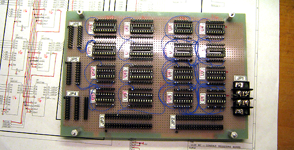
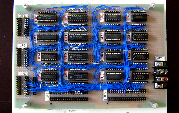
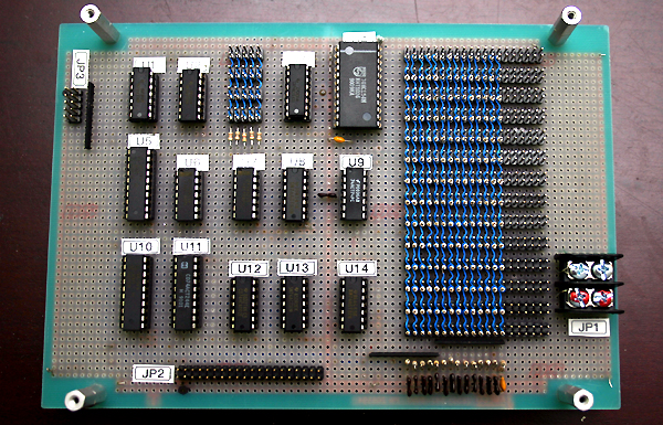
Console Registers board wiring is now complete. The Wiring List proved good as a tool to expedite the task, not sure about accuracy because the board has not been tested yet.
Here is a picture of the board finished:
7/7/2011
This board has not much to do without its Console Controller companion (yet to come). But, since it is hard to test two boards at the same time, I improvised a simple "test board" for firing some control signals via denounced buttons.
A chip burned during the first minute due to a wire mistakenly grounding one of the chip outputs. I was able to catch that and some other wiring mistakes, but tomorrow I plan to perform an "Ohmical" test with all chips removed from their sockets.

This has been my first experience fixing flaws in a wirewrapped circuit. From that I learnt that the low-cost technique employed does not make it easy for correcting wiring mistakes. It seems that, in general, wirewrap and order simply don't match. Wirewrap has to do with "big mess of wires"... on the lower side of the board, not the component side.
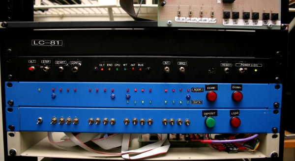
7/19/2011 -- Console Register board is working now
After a long fight, the board seems to work as expected now and, for the first time, I can see my Console monitoring the program execution address by address. Step mode seems to work fine too.
Systematic testing is yet pending by I won't devote too much more time to that. Instead I will start to build the Console Controller board which is the last piece pending for having the MC unit complete.
7/31/2011 -- Prophylaxis leads to system stability
The Console Controller board is on its way but I've kept testing what is built so far. It worked most of the time but occasionally (quite often, I would say) the system got frozen just after power-on so I had to reset it several times until it behaved well again.
I'm testing with a little program burnt in EPROM which writes and reads 55H to all available RAM in a loop. If an error is found (read and written values don't match) the program writes to a location beyond "private memory" so the Console "BUS" lamp illuminates. Then it returns to the loop.
Confident enough that no wiring mistakes were left, I proceed with the "prophylaxis" job.
I started with replacing all bridges between JP2 and its wire-wrap header in the Console Registers board. Those wires were long and formed a buckle very similar to a RF coil so I suspected it could account for cross-talk. I replaced them with short wires.
Then I turned to by-pass capacitors (that I don't normally allocate on all chips). So I put more bypass capacitors.
I also re-soldered some suspicious points on the CPU board and putted more pressure to screws in the power terminal blocks. Also increased the power-on reset capacitor from 1uF to 10uF.
Finally I wondered about grounding.
My power supply has a ground pole connected to the power grid, that I've also connected to the chassis. But my common (in the power supply output) was not connected to ground in any way. I employed my oscilloscope to see if this was causing a problem and, in fact, I saw a "hum" between common and chassis.
What I did to remedy this was to connect the common to chassis by the mean of a capacitor of 0.01 uF. I measured again and confirmed that the hum was gone away.
Done all this, I've kept testing the system to happily find that it seems totally stable now.
I'm getting close, very close --I can't hide my excitement at this very moment.
8/13/2011 -- Diodes Matrix wired
Fixing problems in the Console Registers board took a while because there were at lot of them! But now it is working properly and I'm building the last board pending to complete the MC unit: the Console Controller board.
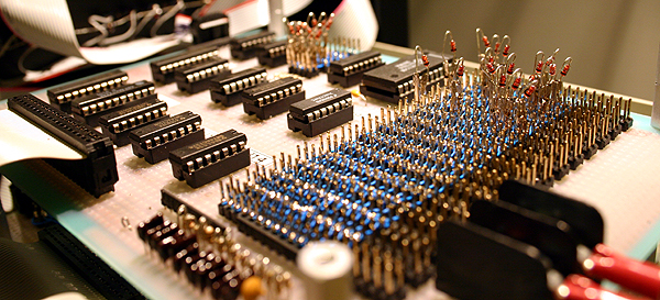
This board relies on a Diodes Matrix to produce the necessary sequences in response to buttons: EXAM-, EXAM+, LOAD, DEPOSIT, that is, memory read and write cycles to/from registers located at the Console Registers board. At this point, the wiring of the Matrix is completed as shown in the picture below.
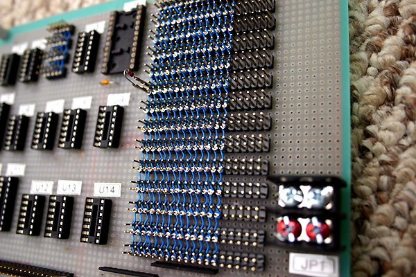
Rows are soldered in the bottom while columns are wirewrapped on the top. Only 14 columns (of the 20 available in the header connectors employed) are needed for the task so only those were wired. Diodes are plugable to which end I crimp them to header pins. This provides the necessary flexibility to fix problems in the Matrix encoding.
In the picture, only one diode is shown but they will be about 50.
I plan to complete the board wiring by the end of this week.
8/22/2011 -- Console Controller wiring complete!
This is the last of the three boards composing the MC Unit. It is shown in the picture below without the (pluggable) diodes.
Testing is pending and, based on my experience with previous boards, I expect a lot of errors! --Nevertheless, I'm closer than ever... hope to have the unit working by the end of this month.
8/23/2011 -- Testing the just born Console Controller board
Today's testing revealed a couple of wiring mistakes. Once fixed, the board started to behave better than what I expected at this point.
I'm trying to test the most I can without diodes mounted on the Matrix so when time comes for testing the "microcode", I can trust the underlying circuitry.
The technique employed for avoiding the sparks produced when a column have consecutive diodes (this was known from my previous project Heritage/1) by using a low-pass filter followed by a schmitt trigger gate, works perfectly: resulting signals are perfectly squared and clean.
In general, the logic seems to work except for the MEREQ/IOREQ discriminator circuit which proved wrong in its design. My next task is to correct this mistake in the fourth revision of the schematic and then apply the corrections to the actual circuit.
So far, so good. I didn't expected anything better.
8/28/2011 -- Console sequences LOAD and DEP are working now
This week has been very busy in terms of trouble-shutting and changes made to the circuits in order to fix the the many problems found. The result could not be better: the first two sequences of the Console (LD and DEP) are finally working.
As mentioned, these sequences are produced by a Diodes Matrix. This technique definitely proved correct and feasible. Compared to microcode stored into EPROM, it presents the advantage of not having the remove the chip from the socket for burning it elsewhere. With the Matrix, one plug and unplug diodes on the fly without even having to turn the machine off.
The technique for producing "plugable diodes", however, can be improved. I'm considering for example to use "jumpers" such as those employed to configure IDE hard drives.
While trying to make the sequences to work I found several problems in circuits design as well as flaws, some of them quite embarrassing... such as missing connections.
Now the Console works partially but steady. I can tab in the entry swithces to define an address, press the LD button, and see how both address and content for that memory location appear correctly displayed in both Address and Data displays. I can also alter memory content by pressing the DEP button.
I have to say that is my first experience operating such a Console and I've found the experience unique and lovely.
The other two sequences (EX+, EX-) should be easy, although some "tricky" details need to be taken into account. I will explain those later (because they are interesting) but for now, I will just post the latest schematics in section Quick Card.
8/30/2011 -- I have a mini!
As suspected, sequences EX- and EX+ were easier: just a matter of placing diodes in the Matrix. Now the Console works so I can declare this unit finished.
Yes, I said "finished", but I can barely believe my self. This unit is what anyone would call the CPU unit. I have called it "Master Controller" (MC) instead to recall my self that I have employed a microprocessor (Z80) which does most of the work. But this unit is indeed, architecturally speaking, nothing but a "CPU Unit"; it does not include any kind of peripheral (such as storage) so it does not make a minicomputer yet.
Nevertheless, it is an important milestone. I will take a couple days to fine-tune it, then I will decide what the next course should be.
12/04/2011 -- Start Address Register (SAR)
A long time since my last post, I know... (busy). Well, here again.
The MC units suffered an important modification: a new register was added to the Console Register Board. This is called "Start Address Register" (SAR) and its mission is, as the name implies, to hold the starting address for the program to run when one presses the START button.
Actually that was the mission of the Lamps Address Register (LAR) so far, according to the previous design as illustrated in the figure below.
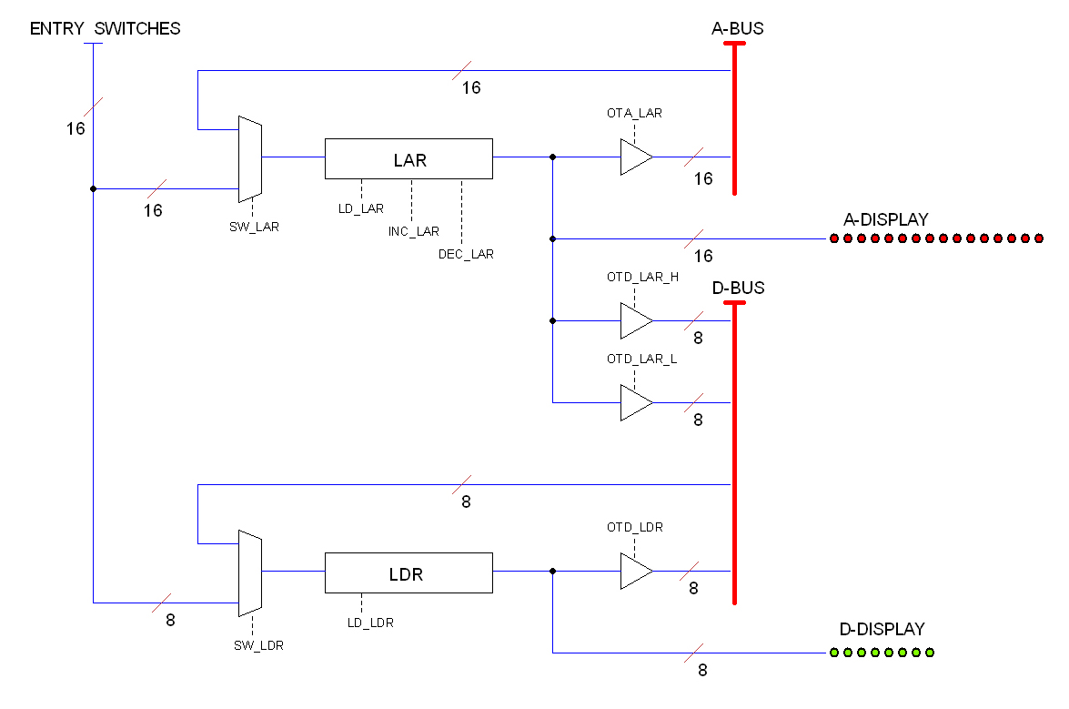
As the program runs, the LAR register is triggered to load the content of the address bus in every read and write cycle. The trigger signal is provided by an "auto-load" circuit located at the Console Controller Board. The LAR output is always displayed in the console address lamps (A-DISPLAY) so the Operator can follow every address accessed in either Run or Halt mode (pressing the EXAM- or EXAM+ buttons).
When the Operator presses the LOAD button, the LAR register loads the content of the Entry Switches, being this the way for the operator to define a starting address for the program to be ran. This worked pretty well except for one little detail: One cannot start a program in Step mode...
The reason is kind of tricky and it has to do with the "auto-load" circuit. I attempted couple of patches to remedy the problem until I decided to go for a clean solution which was the SAR register.
Here is the new circuit (block diagram):
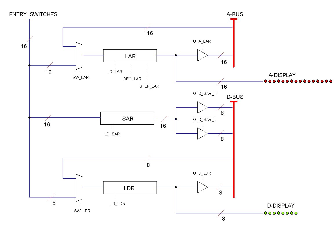
SAR is fed directly from the Entry Switches when the Operator presses the LOAD button. The LAR register gets loaded too so this button continues to serves two purposes: to define the memory location to examine and to define the starting address for the program. But now we have SAR, which does not get disturbed by the "auto-load" circuit so it must hold the starting address no matter what. The only way for overwriting SAR is by pressing the LOAD button again.
Making this simple change in the physical circuit (which is wire-wrapped) was kind of nightmare, proving once again that the cheap wire-wrapping technique employed is not better that my obstinate technique of soldering wires directly in the prototyping board. In effect, making the corresponding changes to the Console Control Board was a lot easier.
12/13/2011 -- Final fix
The implementation of the Start Address Register (SAR) proved correct but not without a fight. It took several days to fix a problem that prevented the unit from starting a program at the given address. Finally the source of the problem was located: it was caused by a collision between the local data bus and that in the EXT-BUS.
Right now the so called EXT-BUS is just a 40-pins header connector at the CPU Board with nothing connected to it (peripherals will be connected here via ribbon cable in the future). The bus stands behind 3rd-state buffers as shown in the schematics: inside this barrier is the "private memory"; outside will be the "external memory" and peripherals, as explained in section Master Controller Unit (MC)
Problem is that the EXT-BUS is not "terminated" yet. My preliminary plan for this was simple: just pull-up 1K resistors, but this had been postponed for a later phase. Problem is that the 3rd-state buffer for the data EXT-BUS is bidirectional (see schematic), so when the CPU reads SAR (which is a peripheral from its point of view) the buffers opens to read data from the EXT-BUS. The erratic value read this way collides with the one been put by SAR in the local data bus.
The remedy for this is to "terminate" the EXT-BUS at once, but for now I just removed the 3rd-state buffer chip. This fixed the problem. Now I can start a program in STEP MODE as intended. The unit is working perfectly now so the first milestone (a functional MC unit) has been finally reached.