ContentAt the time of writing this note, the HASM assembler and the HSIM simultaor are being developed. The true purpose of this manual is to serve as spec to that effort.
Brief description of the minicomputer
Heritage/1 is a 16-bits minicomputer capable of accessing up to 64 Kwords of memory. Peripherals are mapped within the same addressable space.
The minicomputer offers hardware and software interrupts. The later is vectored (8-bits vector supplied in the instruction's argument), the former is not: the 16-bits interrupt address is supplied by the peripheral and loaded directly into the Program Counter. For details on interrupts, refer to section Interrupts Architecture in the Engineer's Manual.
Registers
The CPU has the following (16-bits) registers accessible to the programmer:
General Purpose: B, C, D, E
Special Purpose : Accumulator (A), Program Counter (PC), Stack Pointer (SP), Operand Reg (OR).
The Operand Register (OR) is not thought for programmer's use; however, it is possible (though not recommended) to access it using some "tricks". The mission of the OR register is to read the operand in it during the fetch cycle so it can be available during the exec cycle.
There is also a (6-bits) flags registers (F) to hold the following conditional status:
Z zero
N negative
C carry
V overflow
It also holds the Interrupt Enabled (IE) and Timer Enable (TE) conditions.
The flags register is NOT directly available to programmers. The conditional status is only accesible via conditional branch instructions. Flags IE is accessible via instructions EI, DI.
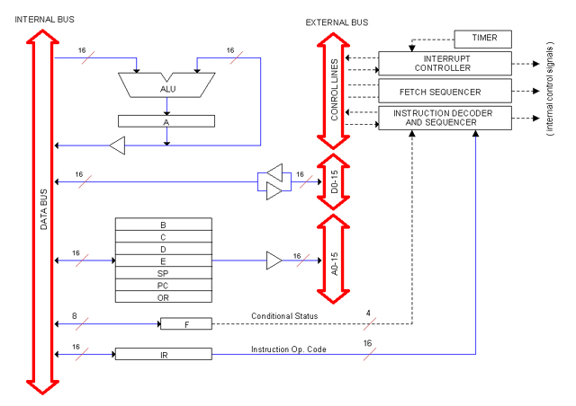
Below is a simplified block diagram of the CPU.
Notice that register A is the only destination for ALU results. Also note that all other registers are double-buffered so they can point to memory by supplying an address directly to the ADDRESS BUS.
The Instructions Set
This section describes the Heritage/1 Instructions Set in great detail from the programmer's prospective. For information on how instructions are actually decoded refer to the Engineers Manual, section Instructions Set Architecture.
Overview
Each instruction (with no exception) takes one word in memory for the operational code (Op Cod). Some instructions take another word for additional data, which we call an "operand".
Arguments (as seen in assembly code) and operands do not necessarilly relate directly since, in most cases, arguments are embedded within the operational code.
Examples:
mvi a, 0x03ff ; The argument 0x03ff represents an operand. The 'a' is embedded in the Op Cod.
mov a, b ; Both arguments (a, b) are embedded within the Op Cod. No operand is employed.
The operational code is fetched in 3 clock periods (750 ns). Instructions with operand employ other 3 clock periods for operand fetching (for a total of 1.5 microseconds). Execution takes between 1 and 8 clock periods depending on the instruction. Average duration for an instruction (both fetch and exec cycles) is 6.5 clock cycles that is 1.6 microseconds.
Addressing Modes
Instructions handle data using one of the following addressing modes.
 Register Register
Data is transferred between CPU registers.
Example:
mov a, b ; a=b coding: 1021
Immediate
A register is loaded with data submitted by the operand.
Example:
mvi a, 0x03ff ; a=03ff coding: 2081 03ff
Direct
Data is transferred between memory and a register. The address is given in the operand.
Example:
ld a, 0x4000 ; a=[4000] coding: 4891 4000
Indirect
Data is transferred between memory and a register. The address is given by another register used as a pointer.
Example:
ldx a, e ; a=[e] coding: 3591
Relative
It is possible to add a given value to the Program Counter (PC) to compute a jump relative to the current instruction; this is termed a "relative branch".
The relative addressing mode can in turn be direct (if the offset value is given by the operand) or indirect (if it is given by a register).
Examples:
jpr 0x0004 ; PC=PC+4 (Relative Direct) coding: 208b 0004
jprx e ; PC=PC+e (Relative Indirect) coding: 259b
Notice that the terms "direct" and "indirect" are not entirely appropriate since data has been given immediately and by a register respectively. However, since the data in question represents an address, we think that "direct" and "indirect" are more intuitive in this case.
Stack
Data is transferred between a register and a memory stack pointed by the Stack Pointer register (SP). Stack instructions are: PUSH and POP.
The Stack grows "backwards", that is, when a word is placed into the stack using the PUCH instruction, SP decrements pointing to the memory located just "above".
The Stack is normally "ready for insertion", that is a PUSH instruction will write first, then decrement the Stack Pointer. A POP instruction will increment SP first, then read.
Instruction Classes
Heritage/1 instructions are divided into "classes". The instruction class is the 4-bits number given by the most significant nibble of the operational code.
Class numbers are not arbitrary but closely related to the way instructions are decoded by the CPU circuitry. So far classes 1 to 11 have been defined; classes 12 to 14 are reserved for future use and class 15 represents a "class extension".
Class 15 instructions utilizes the next nibble (D9-12) to hold the "subclass". Remaining bits are conveniently encoded for the best use of decoding circuitry.
Following is a list of Heritage/1 Instruction Classes.
============================================================================
HERITAGE/1 INSTRUCTION CLASSES AND SUBCLASSES
Note: Even classes and even subclasses require an Operand Fetch cycle
following the Operational Code Fetch Cycle.
============================================================================
CLASS EXT OPND INSTRUCTIONS ADDRESSING MODE
============================================================================
1 . mov r,s reg (ota=0 )
stox r,s indirect (ota<>0 )
jpx r jmp indirect unc. (ld=PC )
jprx r jmp relative indirect unc. (ld=1011)
----------------------------------------------------------------------------
2 x mvi r, value inmediate
sto r, addr direct
jp addr jmp direct unc.
jpr offset jmp relative direct unc.
----------------------------------------------------------------------------
3 . ldx r,s indirect
----------------------------------------------------------------------------
4 x ld r, addr direct
----------------------------------------------------------------------------
5 . add a, r ALU reg
----------------------------------------------------------------------------
6 x adi a, value ALU inmmediate
----------------------------------------------------------------------------
7 . addx a, r ALU indirect
----------------------------------------------------------------------------
8 x addd a, addr ALU direct
----------------------------------------------------------------------------
9 . inc r n/a
dec r
incm r,s
decm r,s
indec r,s
indec implicit
----------------------------------------------------------------------------
10 x jnz addr jmp direct cond.
jnzr offset jmp relative direct cond.
----------------------------------------------------------------------------
11 . jnzx r jmp indirect cond.
jnzrx r jmp relative indirect cond.
----------------------------------------------------------------------------
CLASS EXTENSIONS
----------------------------------------------------------------------------
15 1 . callx call indirect
callrx call relative indirect
----------------------------------------------------------------------------
15 2 x call addr call direct
callr offset call relative direct
----------------------------------------------------------------------------
15 3 . ret n/a
reti
----------------------------------------------------------------------------
15 5 . int vector n/a
----------------------------------------------------------------------------
15 7 . push r stack
pop r stack
----------------------------------------------------------------------------
15 9 . hlt n/a
clrf n/a
di n/a
ei n/a
dt n/a
et n/a
----------------------------------------------------------------------------
Instructions Set
Following is a detailed list of all instructions available in the Heritage/1 minicomputer. The following notation has been used:
Duration is expressed in clock cycles, broke down into: op cod fetch, operand fetch and exec. For example: 3+3+2 means: 3 cycles for op code fetch, 3 for operand fetch and 2 for execution. Total duration is given in microseconds (between parenthesis) assuming a 4 MHz clock frequency.
Register names are written in uppercases (example: A). Identifiers in lowercase indicate generic register (r, s), operand (p), function (g) etc.
Affected flags is expressed with the string: zncv with not-affected flags replaced with dashes (-). For example, the string znc- means that Zero, Negative and Carry flags are affected, Overflow is not.
Generic op cod encoding is written in binary; then a complete list of actual codes is given in hex.
===============================================================
HERITAGE/1 INSTRUCTIONS SET (7/13/2010)
===============================================================
- - - - - - - - - - - - - - - - - - - - - - - - - - - - - - - - -
REGISTER ENCODING
- - - - - - - - - - - - - - - - - - - - - - - - - - - - - - - - -
0001 A
0010 B
0011 C
0100 D
0101 E
0110 SP
0111 PC
1000 OR
1001 MRD (Memory Read signal )
1010 MWR (Memory Write signal )
1011 LDR (LDR_PC: load relative)
- - - - - - - - - - - - - - - - - - - - - - - - - - - - - - - - -
DATA TRANSFER
- - - - - - - - - - - - - - - - - - - - - - - - - - - - - - - - -
Instruction : mov r, s
Descript : Move register
Flags : zn--
Duration : 3+0+2 (1.25 us)
Op cod: 0001 0000 ssss rrrr
r: A B C D E SP PC
s:
A 1011 1012 1013 1014 1015 1016 1017
B 1021 1022 1023 1024 1025 1026 1027
C 1031 1032 1033 1034 1035 1036 1037
D 1041 1042 1043 1044 1045 1046 1047
E 1051 1052 1053 1054 1055 1056 1057
SP 1061 1062 1063 1064 1065 1066 1067
PC 1071 1072 1073 1074 1075 1076 1077
- - - - - - - - - - - - - - - - - - - - - - - - - - - - - - - - -
Instruction : stox r, p
Descript : Store indirect
Flags : zn--
Duration : 3+0+2 (1.25 us)
Op cod: 0001 pppp rrrr 1010
r: A B C D E SP PC
p:
B 121a 122a 123a 124a 125a 126a 127a
C 131a 132a 133a 134a 135a 136a 137a
D 141a 142a 143a 144a 145a 146a 147a
E 151a 152a 153a 154a 155a 156a 157a
SP 161a 162a 163a 164a 165a 166a 167a
PC 171a 172a 173a 174a 175a 176a 177a
- - - - - - - - - - - - - - - - - - - - - - - - - - - - - - - - -
Instruction : mvi value
Descript : Move immediate
Flags : zn--
Duration : 3+3+2 (2 us)
Op cod: 0010 0000 0110 rrrr
r: A B C D E SP PC
2081 2082 2083 2084 2085 2086 2087
- - - - - - - - - - - - - - - - - - - - - - - - - - - - - - - - -
Instruction : sto r, addr
Descript : Store direct
Flags : zn--
Duration : 3+3+2 (2 us)
Op cod: 0010 1000 rrrr 1010
r: A B C D E SP PC
281a 282a 283a 284a 285a 286a 287a
- - - - - - - - - - - - - - - - - - - - - - - - - - - - - - - - -
Instruction : ldx r, p
Descript : Load indirect
Flags : zn--
Duration : 3+0+3 (1.5 us)
Op cod: 0011 pppp 1001 rrrr
r: A B C D E SP PC
p:
B 3291 3292 3293 3294 3295 3296 3297
C 3391 3392 3393 3394 3395 3396 3397
D 3491 3492 3493 3494 3495 3496 3497
E 3591 3592 3593 3594 3595 3596 3597
SP 3691 3692 3693 3694 3695 3696 3697
PC 3791 3792 3793 3794 3795 3796 3797
- - - - - - - - - - - - - - - - - - - - - - - - - - - - - - - - -
Instruction : ld r, addr
Descript : Load direct
Flags : zn--
Duration : 3+3+3 (2.25 us)
Op cod: 0100 1000 1001 rrrr
r: A B C D E SP PC
4891 4892 4893 4894 4895 4896 4897
- - - - - - - - - - - - - - - - - - - - - - - - - - - - - - - - -
ALU
- - - - - - - - - - - - - - - - - - - - - - - - - - - - - - - - -
Register A is always the left operand, as for example:
sub a, b ; a=a-b.
ALU operations are the following:
add Arithmetic add
sub Arithmetic substract
cmp Compare (only flags are affected)
and Logical and
or Logical or
xor Logical exclusive or
shfl Shift left
shfr Shift right
swp Swap MSB and LSB
- - - - - - - - - - - - - - - - - - - - - - - - - - - - - - - - -
Instruction : (various)
Descript : ALU with registers
Flags : znc-
Duration : 3+0+2 (1.25 us)
These instructions operate with A and a register r.
Op cod: 0101 0000 rrrr gggg
r: A B C D E SP PC
g:
ADD 5011 5021 5031 5041 5051 5061 5071
SUB 5012 5022 5032 5042 5052 5062 5072
CMP 5013 5023 5033 5043 5053 5063 5073
AND 5014 5024 5034 5044 5054 5064 5074
OR 5015 5025 5035 5045 5055 5065 5075
XOR 5016 5026 5036 5046 5056 5066 5076
SHFL 5017 5027 5037 5047 5057 5067 5077
SHFR 5018 5028 5038 5048 5058 5068 5078
SWP 5019 5029 5039 5049 5059 5069 5079
- - - - - - - - - - - - - - - - - - - - - - - - - - - - - - - - -
Instruction : (various)
Descript : ALU immediate
Flags : znc-
Duration : 3+3+2 (2 us)
Example:
adi a, VALUE
Op cod: 0110 0000 1000 gggg
ADI 6081
SUBI 6082
CMPI 6083
ANDI 6084
ORI 6085
XORI 6086
- - - - - - - - - - - - - - - - - - - - - - - - - - - - - - - - -
Instruction : (various)
Descript : ALU indirect
Flags : znc-
Duration : 3+0+3 (1.5 us)
Example:
addx a, e
Op cod: 0111 rrrr 1001 gggg
r: B C D E SP PC
g:
ADDX 7291 7391 7491 7591 7691 7791
SUBX 7292 7392 7492 7592 7692 7792
CMPX 7293 7393 7493 7593 7693 7793
ANDX 7294 7394 7494 7594 7694 7794
ORX 7295 7395 7495 7595 7695 7795
XORX 7296 7396 7496 7596 7696 7796
SHFLX 7297 7397 7497 7597 7697 7797
SHFRX 7298 7398 7498 7598 7698 7798
SWPX 7299 7399 7499 7599 7699 7799
- - - - - - - - - - - - - - - - - - - - - - - - - - - - - - - - -
Instruction : (various)
Descript : ALU direct
Flags : znc-
Duration : 3+3+3 (2.25 us)
Example:
addd a, ADDRESS
Op cod: 1000 1000 1001 gggg
ADDD 8891
SUBD 8892
CMPD 8893
ANDD 8894
ORD 8895
XORD 8896
SHFLD 8897
SHFRD 8898
SWPD 8899
- - - - - - - - - - - - - - - - - - - - - - - - - - - - - - - - -
INC / DEC
- - - - - - - - - - - - - - - - - - - - - - - - - - - - - - - - -
Instruction : inc r
Descript : Increment
Flags : zn-v
Duration : 3+0+1 (1 us)
Op cod: 1001 0000 0000 0rrr
r: A B C D E SP
9001 9002 9003 9004 9005 9006
- - - - - - - - - - - - - - - - - - - - - - - - - - - - - - - - -
Instruction : dec r
Descript : Decrement
Flags : zn-v
Duration : 3+0+1 (1 us)
Op cod: 1001 000r rr00 0000
r: A B C D E SP
9040 9080 90c0 9100 9140 9180
- - - - - - - - - - - - - - - - - - - - - - - - - - - - - - - - -
Instruction : incm r, s
Descript : Increment multiple
Flags : zn-v
Duration : 3+0+1 (1 us)
Op cod: 1001 0000 00rr rsss
r: A B C D E SP
s:
A 9009 900a 900b 900c 900d 900e
B 9011 9012 9023 9014 9015 9016
C 9019 901a 901b 901c 901d 901e
D 9021 9022 9023 9024 9025 9026
E 9029 902a 902b 902c 902d 902e
SP 9031 9032 9033 9034 9035 9036
- - - - - - - - - - - - - - - - - - - - - - - - - - - - - - - - -
Instruction : decm r, s
Descript : Decrement multiple
Flags : zn-v
Duration : 3+0+1 (1 us)
Op cod: 1001 rrrs ss00 0000
r: A B C D E SP
s:
A 9240 9280 92c0 9300 9340 9380
B 9440 9480 94c0 9500 9540 9580
C 9640 9680 96c0 9700 9740 9780
D 9840 9880 98c0 9900 9940 9980
E 9a40 9a80 9ac0 9b00 9b40 9b80
SP 9c40 9c80 9cc0 9d00 9d40 9d80
- - - - - - - - - - - - - - - - - - - - - - - - - - - - - - - - -
Instruction : indec r, s
Descript : Increment-Decrement
Flags : zn-v
Duration : 3+0+1 (1 us)
This instruction increments register r and decrements registers s
in a single clock cycle.
If content of any of them changes from 0000 to ffff, both n and v
flags are activated.
If content changes from 0000 to ffff, both n and v flags are activated.
If r=s, the register in question remains unchanged but flags get
activated as result of the decrement operation.
Op cod: 1001 000s ss00 0rrr
r: A B C D E SP
s:
A 9041 9042 9043 9044 9045 9046
B 9081 9082 9083 9084 9085 9086
C 90c1 90c2 90c3 90c4 90c5 90c6
D 9101 9102 9103 9104 9005 9006
E 9141 9142 9143 9144 9145 9146
SP 9181 9182 9183 9184 9185 9186
- - - - - - - - - - - - - - - - - - - - - - - - - - - - - - - - -
Instruction : indec i
Descript : Increment-Decrement implicit
Flags : zn-v
Duration : 3+0+1 (1 us)
This instruction increments registers D, E and decrements registers C
in a single clock cycle.
If content of any of them changes from 0000 to ffff, both n and v flags
are activated.
If content changes from 0000 to ffff, both n and v flags are activated.
Op cod: 1001 0000 1110 0101 (90e5)
- - - - - - - - - - - - - - - - - - - - - - - - - - - - - - - - -
JUMP
- - - - - - - - - - - - - - - - - - - - - - - - - - - - - - - - -
Actual jump occurs with the clock pulse following the jump complete
execution cycle. Conditional jumps will test the associated condition
status from the Flags register. If the condition is not met, execution
will take 1 cycle instead of 2. Unconditional jumps will always jump.
- - - - - - - - - - - - - - - - - - - - - - - - - - - - - - - - -
Instruction : (various)
Descript : Jump direct
Flags : ---
Duration : 3+3+2 (2 us)
Example:
jnz ADDRESS
Op cod (unconditional): 0010 0000 1000 0111
Op cod (conditional) : 1010 0000 1000 ssss
s:
jp 2087
jz a080
jnz a081
jn a082
jnn a083
jc a084
jnc a085
jv a086
jnv a087
- - - - - - - - - - - - - - - - - - - - - - - - - - - - - - - - -
Instruction : (various)
Descript : Jump relative direct
Flags : ---
Duration : 3+3+2 (2 us)
Example:
jnzr OFFSET
Op cod (unconditional): 0010 0000 1000 1011
Op cod (conditional) : 1010 0001 1000 0sss
s:
jpr 208b
jzr a180
jnzr a181
jnr a182
jnnr a183
jcr a184
jncr a185
jvr a186
jnvr a187
- - - - - - - - - - - - - - - - - - - - - - - - - - - - - - - - -
Instruction : (various)
Descript : Jump indirect
Flags : ---
Duration : 3+0+2 (1.25 us)
Example:
jnz e
Op cod (unconditional): 0001 0000 0rrr 0111
Op cod (conditional) : 1011 0000 0rrr 0sss
r: A B C D E SP
s:
jpx 1017 1027 1037 1047 1057 1067
jzx b010 b020 b030 b040 b050 b060
jnzx b011 b021 b031 b041 b051 b061
jnx b012 b022 b032 b042 b052 b062
jnnx b013 b023 b033 b043 b053 b063
jcx b014 b024 b034 b044 b054 b064
jncx b015 b025 b035 b045 b055 b065
jvx b016 b026 b036 b046 b056 b066
jnvx b017 b027 b037 b047 b057 b067
- - - - - - - - - - - - - - - - - - - - - - - - - - - - - - - - -
Instruction : (various)
Descript : Jump relative indirect
Flags : ---
Duration : 3+0+2 (1.25 us)
Example:
jnzrx e
Op cod (unconditional): 0001 0000 rrrr 1011
Op cod (conditional) : 1011 0001 rrrr 1sss
r: A B C D E SP
s:
jprx 101b 102b 103b 104b 105b 106b
jzrx b110 b120 b130 b140 b150 b160
jnzrx b111 b121 b131 b141 b151 b161
jnrx b112 b122 b132 b142 b152 b162
jnnrx b113 b123 b133 b143 b153 b163
jcrx b114 b124 b134 b144 b154 b164
jncrx b115 b125 b135 b145 b155 b165
jvrx b116 b126 b136 b146 b156 b166
jnvrx b117 b127 b137 b147 b157 b167
- - - - - - - - - - - - - - - - - - - - - - - - - - - - - - - - -
CALL, RET and INT
- - - - - - - - - - - - - - - - - - - - - - - - - - - - - - - - -
CALL, RET and INT instructions are the only ones that take more than 4 clock
periods to execute. The extra cycles are required for saving/restoring PC and
F to/from the stack before branching.
These branches are always unconditional.
CALL instructions operate in this order:
- Copy PC to the stack
- Decrement SP
- Copy F to the stack
- Decrement SP
- Load/Add PC with given address/offset
RET instructions operate in this order:
- Increment SP
- Load F from the stack
- Increment SP
- Load PC from the stack
- - - - - - - - - - - - - - - - - - - - - - - - - - - - - - - - -
Instruction : callx r
Descript : Call indirect
Flags : ---
Duration : 3+0+8 (2.25 us)
Op cod: 1111 0001 0000 0rrr
r: A B C D E SP
callx f101 f102 f103 f104 f105 f106
- - - - - - - - - - - - - - - - - - - - - - - - - - - - - - - - -
Instruction : callrx r
Descript : Call relative indirect
Flags : ---
Duration : 3+0+8 (2.25 us)
Op cod: 1111 0001 0001 0rrr
r: A B C D E SP
callrx f111 f112 f113 f114 f115 f116
- - - - - - - - - - - - - - - - - - - - - - - - - - - - - - - - -
Instruction : call addr
Descript : Call direct
Flags : ---
Duration : 3+3+8 (3.5 us)
This instruction saves PC, F to the stack, then branch to the address given
in the operand.
Op cod: 1111 0010 0000 1000 (f208)
- - - - - - - - - - - - - - - - - - - - - - - - - - - - - - - - -
Instruction : callr off_set
Descript : Call relative direct
Flags : ---
Duration : 3+3+8 (3.5 us)
Op cod: 1111 0010 0001 1000 (f218)
- - - - - - - - - - - - - - - - - - - - - - - - - - - - - - - - -
Instruction : ret
Descript : Return from subroutine
Flags : ---
Duration : 3+0+8 (2.25 us)
Op cod: 1111 0011 0000 0000 (f300)
- - - - - - - - - - - - - - - - - - - - - - - - - - - - - - - - -
Instruction : reti
Descript : Return from interrupt
Flags : ---
Duration : 3+0+8 (2.25 us)
Op cod: 1111 0011 0000 0001 (f301)
- - - - - - - - - - - - - - - - - - - - - - - - - - - - - - - - -
Instruction : int vector
Descript : Software Interrupt
Flags : ---
Duration : 3+0+8 (2.25 us)
Op cod: 1111 0101 vvvv vvvv (f5HL) ; HL: vector
- - - - - - - - - - - - - - - - - - - - - - - - - - - - - - - - -
STACK
- - - - - - - - - - - - - - - - - - - - - - - - - - - - - - - - -
Instruction : push
Descript : Insert into the stack
Flags : zn--
Duration : 3+0+3 (1.5 us)
Op cod: 1111 0111 0000 0rrr
r: A B C D E SP PC
f701 f702 f703 f704 f705 f706 f707
- - - - - - - - - - - - - - - - - - - - - - - - - - - - - - - - -
Instruction : pop
Descript : Remove from the stack
Flags : zn--
Duration : 3+0+3 (1.5 us)
Op cod: 1111 0111 0001 0rrr
r: A B C D E SP PC
f711 f712 f713 f714 f715 f716 f717
- - - - - - - - - - - - - - - - - - - - - - - - - - - - - - - - -
MACHINE CONTROL
- - - - - - - - - - - - - - - - - - - - - - - - - - - - - - - - -
Instruction : (various)
Descript : Misc instructions
Flags : ----
Duration : 3+0+1 (1 us)
hlt f900 ; halt
clrf f901 ; clear flags register
di f902 ; disable hardware interrupts
ei f903 ; enable hardware interrupts
dt f904 ; disable Timer interrupt
et f905 ; enable Timer interrupt
Instructions Set Summary
The table below summarizes the Heritage/1 instructions set. The following convention have been adopted to define mnemonics:
The 'i' suffix (as in mvi) indicates immediate addressing
The 'x' suffix (as in ldx) indicates indirect addressing.
The 'r' suffix (as in jnzr) indicates relative addressing (only used in branch instructions).
The 'm' suffix (as in incm) indicates multiple (increment/decrement multiple registers)
The 'd' suffix (as in addd) indicates direct addressing but is not always used.
No suffix indicates register addressing (as in add) except for branch instructions that indicates direct addressing (as in jp).
# REG
------------------------------------------------------------------------------------------------
mnemonic args words cycles flags descript
------------------------------------------------------------------------------------------------
mov r1, r2 1 5 zn-- r1=r2
mvi r, value 2 8 zn-- r=value
ld r, addr 2 9 zn-- r=[addr]
sto r, addr 2 8 ---- [addr]=r
ldx r1, r2 1 6 zn-- r1=[r2]
stox r1, r2 1 5 ---- [r2]=r1
# STACK
------------------------------------------------------------------------------------------------
mnemonic args words cycles flags descript
------------------------------------------------------------------------------------------------
push r 1 5 z--v [sp]=r, sp=sp-1
pop r 1 6 z--v sp=sp+1, r=[sp]
# INC/DEC
------------------------------------------------------------------------------------------------
mnemonic args words cycles flags descript
------------------------------------------------------------------------------------------------
inc r 1 4 zn-v r=r+1
dec r 1 4 zn-v r=r-1
incm r1, r2 1 4 zn-v r1=r1+1, r2=r2+1
decm r1, r2 1 4 zn-v r1=r1-1, r2=r2-1
indec r1, r2 1 4 zn-v r1=r1+1, r2=r2-1
indec implicit 1 4 zn-v C=C-1, D=D+1, E=E+1
# ALU REG
------------------------------------------------------------------------------------------------
mnemonic args words cycles flags descript
------------------------------------------------------------------------------------------------
add a, r 1 5 znc- a=a+r
sub a, r 1 5 znc- a=a-r
cmp a, r 1 5 znc- ?(a-r)
and a, r 1 5 znc- a=a.AND.r
or a, r 1 5 znc- a=a.OR.r
xor a, r 1 5 znc- a=a.XOR.r
shfl a, r 1 5 znc- a=(left-shifted r)
shfr a, r 1 5 znc- a=(right-shifted r)
swp a, r 1 5 znc- a=(swapped r)
# ALU IMMEDIATE
------------------------------------------------------------------------------------------------
mnemonic args words cycles flags descript
------------------------------------------------------------------------------------------------
adi a, value 2 8 znc- a=a+value
subi a, value 2 8 znc- a=a-value
cmpi a, value 2 8 znc- ?(a-value)
andi a, value 2 8 znc- a=a.AND.value
ori a, value 2 8 znc- a=a.OR.value
xori a, value 2 8 znc- a=a.XOR.value
# ALU DIRECT
------------------------------------------------------------------------------------------------
mnemonic args words cycles flags descript
------------------------------------------------------------------------------------------------
addd a, addr 2 9 znc- a=a+[addr]
subd a, addr 2 9 znc- a=a-[addr]
cmpd a, addr 2 9 znc- ?(a-[addr])
andd a, addr 2 9 znc- a=a.AND.[addr]
ord a, addr 2 9 znc- a=a.OR.[addr]
xord a, addr 2 9 znc- a=a.XOR.[addr]
shfld a, addr 2 9 znc- a=(left-shifted [addr])
shfrd a, addr 2 9 znc- a=(right-shifted [addr])
swpd a, addr 2 9 znc- a=(swapped [addr])
# ALU INDIRECT
------------------------------------------------------------------------------------------------
mnemonic args words cycles flags descript
------------------------------------------------------------------------------------------------
addx a, r 1 9 znc- a=a+[r]
subx a, r 1 9 znc- a=a-[r]
cmpx a, r 1 9 znc- ?(a-[r])
andx a, r 1 9 znc- a=a.AND.[r]
orx a, r 1 9 znc- a=a.OR.[r]
xorx a, r 1 9 znc- a=a.XOR.[r]
shflx a, r 1 9 znc- a=(left-shifted [r])
shfrx a, r 1 9 znc- a=(right-shifted [r])
swpx a, r 1 9 znc- a=(swapped [r])
# JUMP DIRECT
------------------------------------------------------------------------------------------------
mnemonic args words cycles flags descript
------------------------------------------------------------------------------------------------
jp addr 2 8 ---- pc=addr unconditional
jz addr 2 8 ---- pc=addr if zero
jnz addr 2 8 ---- pc=addr if non zero
jn addr 2 8 ---- pc=addr if negative
jnn addr 2 8 ---- pc=addr if non negative
jc addr 2 8 ---- pc=addr if carry
jnc addr 2 8 ---- pc=addr if non carry
jv addr 2 8 ---- pc=addr if overflow
jnv addr 2 8 ---- pc=addr if non overflow
# JUMP INDIRECT
------------------------------------------------------------------------------------------------
mnemonic args words cycles flags descript
------------------------------------------------------------------------------------------------
jpx r 1 5 ---- pc=r unconditional
jzx r 1 5 ---- pc=r if zero
jnzx r 1 5 ---- pc=r if non zero
jnx r 1 5 ---- pc=r if negative
jnnx r 1 5 ---- pc=r if non negative
jcx r 1 5 ---- pc=r if carry
jncx r 1 5 ---- pc=r if non carry
jvx r 1 5 ---- pc=r if overflow
jnvx r 1 5 ---- pc=r if non overflow
# JUMP RELATIVE DIRECT
------------------------------------------------------------------------------------------------
mnemonic args words cycles flags descript
------------------------------------------------------------------------------------------------
jpr offset 2 8 ---- pc=pc+offset unconditional
jzr offset 2 8 ---- pc=pc+offset if zero
jnzr offset 2 8 ---- pc=pc+offset if non zero
jnr offset 2 8 ---- pc=pc+offset if negative
jnnr offset 2 8 ---- pc=pc+offset if non negative
jcr offset 2 8 ---- pc=pc+offset if carry
jncr offset 2 8 ---- pc=pc+offset if non carry
jvr offset 2 8 ---- pc=pc+offset if overflow
jnvr offset 2 8 ---- pc=pc+offset if non overflow
JUMP RELATIVE INDIRECT
------------------------------------------------------------------------------------------------
mnemonic args words cycles flags descript
------------------------------------------------------------------------------------------------
jprx r 1 5 ---- pc=pc+r unconditional
jzrx r 1 5 ---- pc=pc+r if zero
jnzrx r 1 5 ---- pc=pc+r if non zero
jnrx r 1 5 ---- pc=pc+r if negative
jnnrx r 1 5 ---- pc=pc+r if non negative
jcrx r 1 5 ---- pc=pc+r if carry
jncrx r 1 5 ---- pc=pc+r if non carry
jvrx r 1 5 ---- pc=pc+r if overflow
jnvrx r 1 5 ---- pc=pc+r if non overflow
# CALL AND RET
------------------------------------------------------------------------------------------------
mnemonic args words cycles flags descript
------------------------------------------------------------------------------------------------
call addr 2 14 ---- [sp]=f, sp=sp-1, [sp]=pc, sp=sp-1, pc=addr
callx r 1 11 ---- [sp]=f, sp=sp-1, [sp]=pc, sp=sp-1, pc=r
callr offset 2 14 ---- [sp]=f, sp=sp-1, [sp]=pc, sp=sp-1, pc=pc+offset
callrx r 1 11 ---- [sp]=f, sp=sp-1, [sp]=pc, sp=sp-1, pc=pc+r
ret 1 11 ---- sp=sp+1, pc=[sp], sp=sp+1, f=[sp]
reti 1 11 ---- sp=sp+1, pc=[sp], sp=sp+1, f=[sp], /SIE=0
# MISC
------------------------------------------------------------------------------------------------
mnemonic args words cycles flags descript
------------------------------------------------------------------------------------------------
hlt 1 4 ---- halt the machine
clrf 1 4 zncv clear flags
int vector 1 11 ---- [sp]=f, sp=sp-1, [sp]=pc, sp=sp-1, pc=[vector]
ei 1 4 ---- enable hardware interrupts
di 1 4 ---- disable hardware interrupts
et 1 4 ---- enable timer
dt 1 4 ---- disable timer
------------------------------------------------------------------------------------------------
The H1ASM assembler (v.0)
H1ASM v.0 is a rudimentary two-passes assembler designed to directly produce executable code for the Heritage/1 minicomputer. This tool is written in PHP command-line interface (CLI) to be ran at a modern Personal Computer under Linux, Windows or Mac OS-X. Resulting executable code needs to be transfered to the target minicomputer in the form of a binary file.
Overview
The H1ASM v.0 assembler is designed to work without a Linker companion; the assembler directly produces executable code, implying that it will not export symbols and it won't work with precompiled object code or libraries which is indeed a limitation.
It does, however, accept source file inclusion which allows for organizing a large project into manageable source modules. It also implements the notion of variable which, combined with file inclusion, will hopefully help in writing structured, reusable, maintainable code.
Macros, conditional compilation, pseudoinstructions and other advanced features are not implemented in this version but plans exist for provide those in the near future.
Launching the assembler program
The assembler's main file is a PHP script named: h1asm.php. Assuming you have exec writes on that script, you launch the assembler with the following command:
h1asm.php main_src_file_path include_dir
The first argument is a path to the intended main source file. The second argument is optional and refers to the directory where included files are located; if missing, the assembler will extract the include directory from the first argument assuming that the main file is placed together with all included files.
Anatomy of assembly code
The assembler processes the source file one line at a time. Lines are trimmed before processing so leading spaces and tab characters can be inserted for better formatting if desired. Each line could be one of the following types:
- Blank line : Will be ignored
- Comment : Starts with semicolon (;)
- Instruction : Syntactically valid Hieritage/1 instruction
- Label : Symbolic address. Start with colon (:)
- Symbol definition : In the form SYMBOL equ VALUE, or: #define SYMBOL = VALUE
- Origin directive : In the form #org ADDRESS
- Data directive : In the form #data EXPRESSION
- Output Format directive : In the form #format FORMAT
- Include directive : In the form #include FILE_NAME
Comments cannot appear in a line that is not a comment. Following is an example of acceptable assembly code.
; Listing #1
; ----------------------------------------------------
; HERITAGE/1 -- SAMPLE ASSEMBLY CODE
; ----------------------------------------------------
; This code implements INT 7 both vector and handler code
; for copying BUFF_SIZE words from BUFF_SRC to BUFF_DES
;
#format H12
#include vectors.equ
INT_7_CODE equ 0x0400
BUFF_SRC equ 0x4000
BUFF_DES equ 0x0800
BUFF_SIZE equ 0x0020
#org INT_7_VECTOR
#data INT_7_CODE
#org INT_7_CODE
mvi c, BUFF_SIZE
mvi d, BUFF_SRC
mvi e, BUFF_DES
:LOOP
ldx a, d
stoxa, e
inc d
inc e
dec c
jnz LOOP
jp QUIT
; garbage, just to justify the forward jump
#data 0xffff
:QUIT
ret
Assembler Output
The assembly process results in two files:
- Code file (.bin) : Executable (binary) code.
- Listing file (.lst) : As built (ASCII) listing of source with numeric
addresses and error messages if any as well as
extra info such as the Symbols Table.
The assembler creates their filenames from the source filename by replacing the file extension with .lst and .bin respectively.
The code file (.bin) is built acording to one of the following formats (indicated in code by the directive #format FORMAT):
- H10 : Exact image of code in memory using relative branch instructions only.
- H11 : Monolithic code with header specifying the ORG address.
- H12 : Fragmented code with header specifying different ORG addresses.
- H13 : Relocatable code with header indicating words (off-sets) in need
for relocation.
These different formats are targeted to different operational environment that the target computer may offer. At early stage of development, no operational environment exists so formats H10 and H11 are the most appropriate. Format H12 is useful for full memory dumping including vectors (such as in Listing #1). Format H13 is better suited for applications in presence of a Loader capable of relocation.
If #format H10 is specified, the Assembler will translate absolute branch instructions to relative ones, automatically. If the directive is missing, format H12 will be assumed.
Error reporting
The assembler reports errors in the Listing file (.lst) in the form of single-line messages inserted right after the line where the error was found. The code file (.bin) will not be produced if errors have occurred.
There is no distinction between "errors" and "warning"; errors are simply errors and will be reported as such.
Error checking depends on the targeted format. For example, duplicated #org directives will be reported if H11 format was requested.
Syntax Details
Expressions
Expressions are used to directly represent numbers or strings. Since arithmetic operations are not included in the current assembly language, expressions are nothing but "literals".
As Heritage/1 is a strict 16-bits machine (memory is organized in 16-bits words), numerical expressions are always 16-bits integers (singed or unsigned) and values greater than 65,535 will generate overflow errors at assembling-time. Bytes (8-bits) are NOT represented within assembly code in any way. NOTE: A notable exception to this is the instruction INT which takes an 8-bits vector number as argument in assembly code (this byte is actually embedded within the op. code); in this case the argument is written as a normal 16-bits word although the assembler will report overflow error if it is greater than 0x00ff.
The following numerical expressions are valid:
---------------------------------------------
0x03ff Hexadecimal
0b010101 Binary
44 Decimal
-44 Decimal negative
65000 Decimal. Valid but it may represent a negative binary (two's complement)
The following expressions are illegal:
--------------------------------------
-0x03ff Only decimals can be explicitly signed.
68456 Overflow.
64,000 Commas as delimiters in numbers are not accepted.
A string is a null-terminated sequence of ASCII characters occupying a 16-bits word each (the assembler fills the MSB with zeros). The null termination consists of a word with all bits cleared.
Strings are written in assembly code starting with dollar sign ($) as in the following example:
:ERROR_MSGS
#data $Drive not on-line
#data $Volume not mounted on drive
A words about signed and unsigned integers
The Heritage/1 ALU makes use of two's complement arithmetic for adding and subtracting 16-bits numbers. However, this does not limit the programmer to the use of signed integers in assembly code, as signed or unsigned is mostly a matter of interpretation.
For instance, using the instruction ADD for adding 0xf000 to 0x0001 will result in 0xf001 which can be interpreted either as positive 61441 or negative or -4095. Moreover, when building more powerful arithmetic by software (such as BCD or Floating Point) the programmer is responsibly for defining data types and to make the correct representation and interpretation of the arithmetic sign.
Symbols
Simply put, symbols represent expressions. You define symbols by using the directive #define or the equ construct. The assembler also auto-define some symbols (labels in particular) while parsing the code; in the following example, the value for label QUIT is not given explicitly but calculated by the assembler.
; Listing #2
; Examples of symbols used as both address and data
;
STU_STOP equ 0x0000
CMD_RWD equ 0x0004
TAPE_REG equ 0x4000
START equ 0x0400
#org START
; Check if tape is stopped.
ld a, TAPE_REG
cmp STU_STOP
jnz QUIT
; Sent Rewind command to the tape driver:
mvi a, CMD_RWD
sto a, TAPE_REG
:QUIT
hlt
As seen in code, a valid symbol contains nothing but alphabetic and numeral characters as well as underscores ( _ ). The length is restricted to 40 characters and the first one can not be numeric.
Each symbol must be defined only once in the entire project scope, so caution must be observed specially with large projects composed by many files. Duplicated symbols will be reported as errors.
Variables
Variables differ from symbols in that they can appear more than once within the code. You assign a value (either a symbol, an expression or another variable) to a variable by using the #set directive.
Variables don't need to be defined as they get auto-defined with the first assignment encountered during the parsing process.
The following statements are valid:
#set foo = 0x044
#set foo = SOME_SYMBOL
#set other_var = foo
Directives
By directive we understand those commands placed in assembly code that are targeted to the Assembler, as opposite to instructions which are targeted to the computer running the resulting binary code.
Directives start with the sharp character (#) followed by the directive's name, then the argument. These three parts are separated from each other by the mean of spaces or tabs.
The following directives are currently available.
Include
Syntax:
#include FILE_NAME
This directive causes the given file (FILE_NAME) to be opened and processed immediately as if it were part of the current file. This action is recursive so further #include directives found in included file will be processed in the encountered order.
The #include's argument (FILE_NAME) is the name of a source file expected to be in the "include directory"; the later was passed explicitly in the command line (second argument) when the assembler was launched, or was automatically extracted otherwise from the source-file path (first argument) at that time.
You can also specify a full path in the #include directive. That may be the case of being using reusable code from files placed in separate directories for better organization. The assembler will realize whether the #include argument is a filename or a full path and it will act accordingly. Either case, if the file does not exist, an error will be reported.
A given file can be #included more than once. This might be used to compensate for the lack of Macros, as in the following example:
; Using reusable code for sorting a list in memory.
; The included code accepts arguments in registers d, c.
mvi d, BUFF ; List in memory to be sort out
ld c, BUFF_SIZE ; Certain var in memory holding the buffer's size
; The included code does the job...
#include /home/armando/src/lib/quick_sort.asm
Org
Syntax:
#org ADDRESS
Sets the origin address, effective since the first instruction following the directive's line. ADDRESS can be either a symbol or a numerical expression.
The following statements are valid:
START equ 0x400
#org START
#org 0x400
The following will result in error: "Illegal use of string":
#org $START
Data
Syntax:
#data EXPRESSION
This directive is useful for filling areas of memory with fixed data such as lookup tables and string messages, as illustrated below.
#define MSG_TABLE = 0x800
#org MSG_TABLE
#data $File not found
#data $Stack overflow
Starting at address 0x800 will be the (null-terminated) string "File not found" followed by the string "Stack overflow" (30 words total).
Define
Syntax:
#define SYMBOL = VALUE
This directive defines a symbol by indicating the expression (VALUE) it represents. The same can also be done with the equ construct for numeric expressions as illustrated in previous examples.
Actually, support for equ was introduced in H1ASM for compatibility with such "traditional" construct. However, the #define directive is conceptually more robust and more powerful in practice since it allows for symbolic strings too.
The previous example could also be written this way:
#define MSG_TABLE = 0x800
#define ERR_MSG_F_NOFOUND = $File not found
#define ERR_MSG_S_OV = $Stack overflow
:MSG_TABLE
#data ERR_MSG_F_NOFOUND
#data ERR_MSG_S_OV
Set
Syntax:
#set VAR = VALUE
The set directive is used to assign a value to a variable. If the variable didn't exist, it is created at that time. VALUE can be either a symbol, an expression, another variable or even the same variable (which doesn't sound too much useful but it is legal anyways).
Once a variable is created, it can be used in instructions in place of the operand, as illustrated in the following example.
#define BUFF_TAPE_1 = 0x4000
#define BUFF_TAPE_2 = 0x4100
; Call subroutine passing argument in variable:
#set @_buff = BUFF_TAPE_1
call READ_TAPE
; Call subroutine again passing a different argument in the same variable:
#set @_buf = BUFF_TAPE_2
call READ_TAPE
;
; -- SUBROUTINE --
;
:READ_TAPE
; Variable used as operand:
ld e, @_buff
Symbols and variables can not share names; failure to observe this will result in errors reported by the assembler. To overcome this limitation, naming conventions must be employed. We suggest to write symbols with uppercases and variables, written with lowercases, to start with the '@' character as illustrated in the previous example.
The need for variables comes from the lack of macros in H1ASM. In fact, you can "encapsulate" reusable generic code into separate source files, then #include it in your "client code" passing arguments through variables. Here is an example:
#set @_quick_sort_buff = BUFF_ADDR
#set @_quick_sort_buff_size = BUFF_SIZE_VAR
; The included code does the job. It uses the above variables:
#include /home/armando/src/h1_lib/quick_sort.asm
Format
Syntax:
#format FORMAT
Specifies the output format as explained in section Assembler Output.
Instructions
Output File Format Details
The H1SIM simulator
At the time this section is being written, the Heritage/1 minicomputer is not finished yet. The purpose of writing this section at this early time is to provide a "spec" to my self for the development of the H1SIM simulator.
Overview
H1SIM is a rudimentary simulator which main purpose is to test developing software using a modern PC rather than the target minicomputer. H1SIM does not emulate the Heritage/1 circuitry but solely its behavior and it does it, not in real-time but at the PC's speed which is obviously much faster.
H1SIM is written in PHP command-interface (CLI) and employs a command-based user interface. The scenario for its action is an internal representation of the Heritage/1 memory (MEM). Different commands are provided to load content into MEM from files or directly from the command interface as if it was entered in the minicomputer using the Console's Entry Switches.
Programs in particular can be loaded from the same binary files produced by the H1ASM assembler. Once in MEM, those programs can be "executed"; the execution results in changes to MEM content that can then be dumped into human-readable (ASCII) files or directly to the standard output for immediate inspection. Programs can also be ran in "step mode".
H1SIM also offers a number of debug capabilities nowadays found in modern debuggers, such as the ability to define break points and watches. Other features include: disassembling to Listing files similar to those produced by the H1ASM assembler, binary file manipulation and others.
Hardware interrupts can be simulated though with certain limitations as we shall see. Peripherals emulation is not directly provided but the program can be extended with custom PHP scripts to implement such capabilities. Guidance for doing so is provided in this manual.
The H1OS Operating System
These notes describe the very first approach to an Operating System (H1OS) which development has not started yet.
H1OS is planed to be a "simple" multiprogramming operating system oriented to batch processing offering support for tapes as the only storage mean. Some of its features may look bizarre as seen from our modern prospective but that's only because H1OS has been designed for a batch processing work flow as opposite as nowadays familiar interactive multi-user environments. Actullay, H1OS is not meant to be innovative in any respect but just to do the job in a simple way.
Overview
H1OS is oriented to batch processing and tapes. It employs multiprogramming to allow up to 16 processes to run at the same (scheduled) time. It does not implement the notion of "user": the "Monitor" (command interpreter) is intended to a professional operator and employs a dedicated terminal for it. Applications are not supposed to be interactive but the OS does not prevent the programmer from doing so in which case a separate terminal will be required for that purpose.
H1OS does not implement protected mode either as the Heritage/1 minicomputer does not offer support for that. Different processes are given separate stacks but those share the same physical (64K) address space. Preemptive scheduling does its best for isolating misbehaving processes but nothing can prevent a buggy program from corrupting other's processes code or data or even those for the Operating System itself.
System configuration relies heavily on the operator who will need to setup applications before they run. The setup of a particular program includes manual assignment of resources such as tape drives, printers and terminals. Loading/Unloading of Run-Time Libraries, as well as other OS-related task are also under the Operator's control. Most of this work, however, can be automated by the use of configuration files residing on tape.
If non of this sounds too much inviting... welcome to the Heritage/1 world!
Architecture
The H1OS Operating System consists of a Kernel and a set of Service Processes.
The Kernel is a set of independent routines providing basic functionality such as memory allocation and low-level access to peripherals. These routines are invoked from applications by the mean of "system calls" consisting of software interrupts. Kernel routines are said to be "critical" as they must execute from top to bottom without interruptions hence they must be designed to return rapidly in order to avoid system "freezing". Among these Kernel routines is the processes Scheduler.
Service processes are long-term execution programs sharing a time-sliced space that we call the "Multiprogramming Space" (MPS) under the Scheduler's control. As opposite, we define the notion of "Kernel Programming Space" (KPS) to refer to the "critical-region" code occurrence. Application and OS Service Processes share the same MPS. Among Service Processes is the commands interpreter or Monitor which provides the human interface for the Operator.
A key distinction between KPS and MPS code is that the former utilizes fixed global variables located in a dedicated portion of the memory addressing space that we call the "Kernel Data Area" whereas the later utilizes memory granted by the OS upon request, located in the Heap.
Apart from the Kernel, Monitor and OS Services, the Operating System allows for installable Run-Time Libraries (RTL) such as those provided by languages. RTL code is placed in the Heap and executes either in the MPS or the KPS as we shall see later.
Memory Map
From the OS prospective the computer's memory is divided in the following portions:
------------------------------------------------------------------
H1OS MEMORY MAP
------------------------------------------------------------------
0000-00ff (256 words ): Interrupt Vectors
0100-1fff (rest of 8K): Kernel Data Area followed by Kernel Code
2000-... (4K to 52K ): Heap
f000-ffff (4K ): Peripheral dual-port buffers
------------------------------------------------------------------
Interrupt vectors are used by both internal CPU-generated interrupts and software interrupts (See Interrupts Architecture in the Engineer's Manual for details).
The Kernel Data Area holds different global structures used by the Kernel such as the Process Schedule Table and the Memory Allocation Table among many others.
Kernel code follows. As mentioned, this is a set of separate short routines placed one after another.
Starting at address 2000 is the Heap (remaining memory) where all application code and data will be allocated. Operating System service processes and Run-Time Libraries are also placed in this area.
The Heap is managed by the Kernel in terms of "paragraphs" of 256 words each. As Heritage/1 memory increments in steps of 4K words, the size of the Heap can expand from 16 paragraphs (4K) to 32 paragraphs (52K).
The bottom 4K portion of the addressable space (f000-ffff) is not populated with actual RAM chips installed in the Core Unit but reserved for peripherals. In this range, peripherals will allocate their buffers which are wired as dual-port memory. Buffers may be of different sizes depending of the peripheral's design.
A typical configuration will have 32K words of RAM installed in the Core Unit from 0000 to 7fff. This makes a Heap of 24K words. The bottom portion (f000-ffff) will still reserved for peripherals dual-port buffers.
|