Backplane
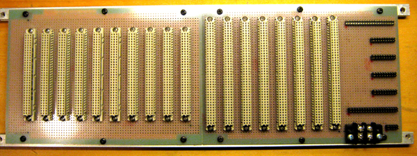
The Backplane consists of ten 96-pins and eight 120-pins DIN 41612 female connectors, seven header connectors and one 2-POS terminal block connector. This later is for power supply (5V).
Each DIN connector occupies a "Slot"; these are enumerated from left to right: Slot#1... Slot#18. The terminal block connector is termed JP1. Headers are enumerated from bottom to top: JP2... JP8.
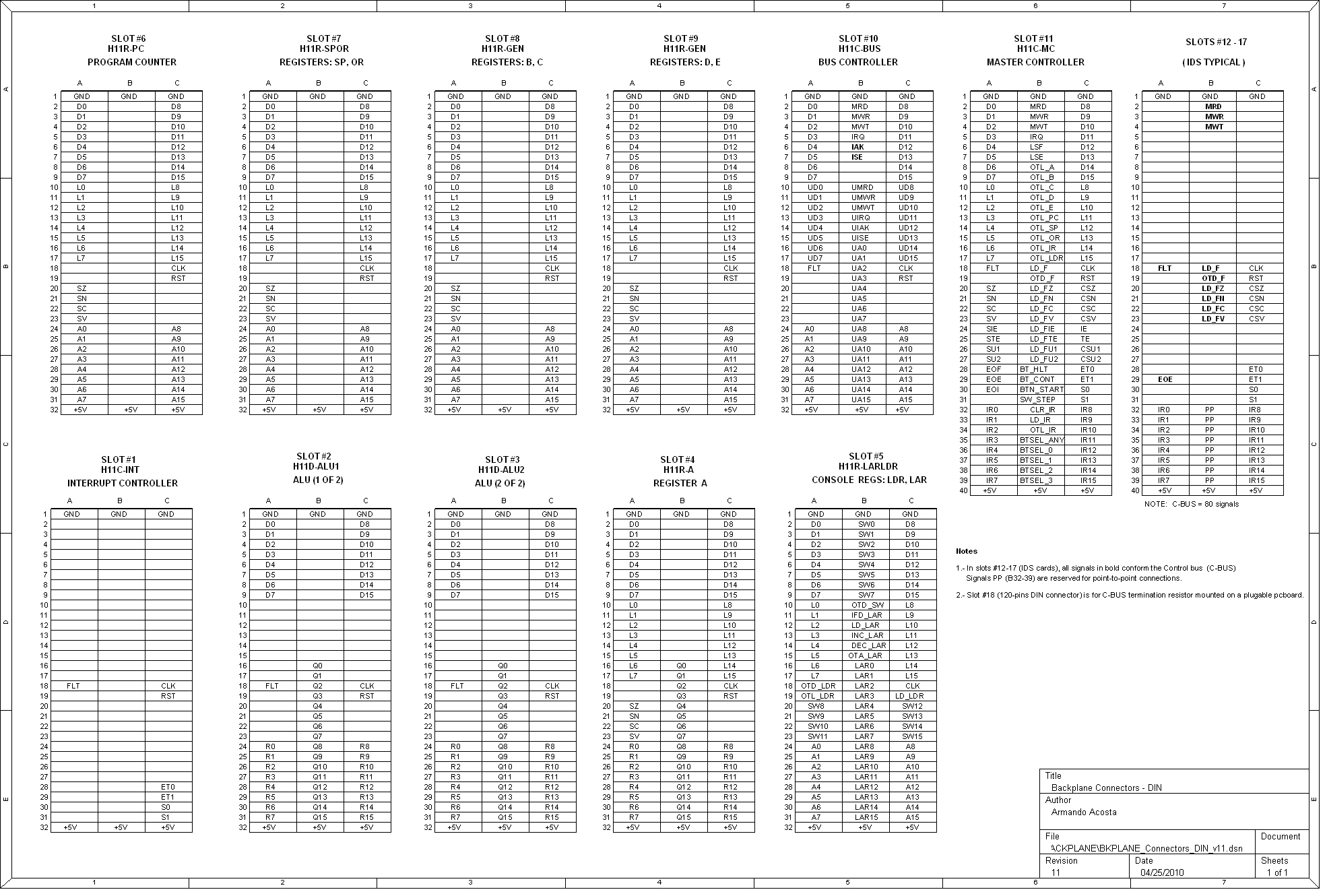
All connectors are wired in the back to compose the various internal buses of the CPU. Some Point-To-Point connections between different Slots also exists. Termination resitors for internal buses are placed (soldered) in the backplane.
|
Homebuilt CPUs WebRing
JavaScript by Qirien Dhaela
Join the ring?
David Brooks, the designer of the Simplex-III homebrew computer, has founded the Homebuilt CPUs Web Ring. To join, drop David a line, mentioning your page's URL. He will then add it to the list.
You will need to copy this code fragment into your page.
Project start date: May 13 of 2009
|