First Approach to ImplementationSimplified Memory Management
05/23/2009
The justification to simplify existing Memory Management techniques is that I want to explore those concepts in a manageable way so not get lost with complicated details. After all, it is not my intention to produce a commercial computer.
Physical Memory
Physical memory is wired in 32 bits rows meaning that the data bus is 32 bits wide.
However, physical addresses refer to 8 bits chunks. For example, the address range: 0x01 - 0x10, represents a zone of 16 bytes, not 64 bytes. This is done by making the address bus from A31 to A2 as in the Pentium processors. Unlike Pentium, however, I will not allow bus cycles to get 8 nor 16 bits; instead, all bus cycles will always read or write a 32 bits row (four bytes at once).
This arrangement dictates (or suggest) other decisions such as: Instruction code must be 32 bits, CPU registers must be 32 bits though "splitable" into 16 and 8 bits so different data types can be available to the programmer, etc.
Linear Model
Applications will see memory as a Linear space of 2^32 bytes (4GB). As for physical memory, each increment in the Linear address represents one byte, not one 32 bits row. For example, for getting 8 contiguous bytes, the application may issue the following linear addresses: 0x01, 0x05 (not 0x01, 0x02).
Application code will be linked to produce linear addresses. Often, same addresses will appear repeated among different applications running simultaneously at a given time. For the CPU, however, application addresses represent nothing but offsets (indexes) within the designated space which only translate to physical addresses at the very bus-cycle time (by hardware).
Each application will believe that it owns the entire 4GB linear space. This illusion will connect to reality at translation time into the CPU circuitry.
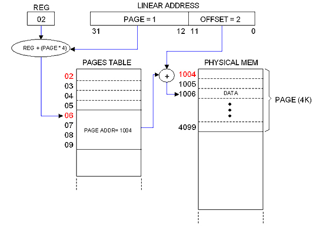
Paging
The image below illustrates my simplified paging mechanism which mission is to implement linear-to-physical Address Translation and Global Protection.
The linear address is broken into two fields: PAGE (20 bits) and OFFSET (12 bits). This allows for 2^20 pages, 4KB each.
Pages are described in the PAGE TABLE. Each entry in the table takes 4 bytes representing bit-mapped fields. One of these fields (20 bits long) is the "Page Address" which is the base physical address for the referred page. The other fields are used for Protection.
The PAGES TABLE entry is obtained from the PAGE field of the Linear Address and a certain register (REG) which hold the base address for the Table. The PAGE field actually represents an index.
The OFFSET field of the Linear Address provides the index within the given physical page to compute the translated physical address, as illustrated in the diagram.
One Pages Table for each running process
Since, as mentioned, each process believes to own the entire linear address space, one Pages Table for each process is needed. I will cover this in a separate note dedicated to Processes.
The 4MB frontier
The Pages Table can be as small as 4 bytes or as big as 4MB. However, its natural size is 4KB (one page frame) because that is the granularity of memory allocation.
A Pages Table of 4KB has 1024 entries which describes 1024 pages, that is, 4MB of physical memory. Hence 4MB becomes a "natural frontier" for physical memory.
Therefore, it sounds natural to establish that the machine's memory will be expandable in steps of 4MB. Besides, 4MB of static RAM is about $100 at today's prices... definitely a reasonable frontier!
Limitation of my one-step paging mechanism
The Pages Table occupies a contiguous space in physical memory. It can expand to a maximum of 4 MB (2^20 entries times 4 bytes) but in practice it will be shorter since entries will be added as memory gets allocated.
This design imposes a limitation to the size of the Linear space: It cannot be greater that the greater physical address available. Otherwise, I will be forced to popultate the entire 4MB table to accomodate all possible linear addresses.
The system can still commit more memory than the physical memory available. What it cannot is to commit a Linear address for which an entry in the Pages Table does not exist.
That is the price to pay for my simplified one-step paging mechanism.
First approach to Paging implementation
05/23/2009
In previous note (Simplified Memory Management) I suggested that Pages Tables will take room from physical memory address space, but that is not true.
-- NOTE: --
I've borrowed most of the terminology from Intel literature but that "Pages Table" sounds ugly to me... I will call it "Translation Table" from now on, or simply "Trans Table".
-----------
I mentioned that it should be one separate Trans Table for each running process (since each process should be into believe that it owns the entire linear space). If I content my self to limit the number of simultaneous processes to a practical value, then I can afford to build a separate "room" in the CPU, out of the addressable RAM, to host all Trans Tables ever needed.
Let set the limits:
-- Max number of simultaneous processes: 128
-- Max RAM size: (Conceptually: 4 GB) expandable in steps of 4BM.
The "room" will be a SRAM matrix of 128K x 32 (using four 128K x 8 chips) expandable in steps of 128K x 32 (four chips). I will call this: the "Trans Matrix" or simply "Matrix".
Each row in the Matrix represents a Trans Table entry. With 4MB of RAM in the computer (1024 pages), 1K rows covers the entire linear space for that amount of physical memory. Therefore, with 128K rows at my disposal I can give one entire Trans Table to each of the 128 allowed processes.
As mentioned, expansion is possible (and easy). The only thing is that, as RAM expands, the Trans Matrix must be expanded accordingly. It would be better, maybe, to place the Matrix on the memory card, disributed among them in case that more than one exist.
System software is responsible for populating the Matrix. I will create the appropriate Supervisor instructions for doing that. Please notice that the Matrix needs to be updated as processes get alive and die, not only at boot up time.
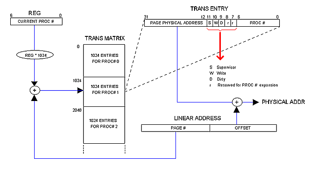
Close up to the Trans Matrix
05/23/2009
The following diagram illustrates how the Trans Matrix participates in address translation and protection.
The Matrix holds a record (1024 rows deep) for each running process. Each record constitutes the process Trans Table, that is, the space available for the process to allocate the 1024 possible Trans entries.
Each process has a process number (PROC #). The current proc # is kept in certain register (REG in the diagram) as long as the process is running. That number is used as an index to access the corresponding record. The PAGE field of the Linear address is used, in turn, as an index within the record to locate the exact Trans Table entry.
As mentioned in previous notes, the Trans Entry contains the physical base address for the page in physical memory. It also contains the following control fields:
S Set if the page is for Supervisor use only
W Set if writing on this page is permitted
D Set is the page have been modified
r Reserved for future expansion
PROC # Process number
There is a reason for including the PROC #.
I mentioned in a previous note (Limitation of my one-step paging mechanism) that the Linear space available to applications is limited far below 2^32. If a buggy code submits a linear address that exceeds the limit, chances are for the Address Translation mechanism to compute an entry that is valid but belongs to the wrong process. To avoid this, the CPU will always verify that the PROC # field matches the content of REG before proceeding with Address Translation. Besides, stamping each process page with the Proc# seems to me an elegant way of assuring that inter-processes interferience will not occur.
Scalability Issue
05/25/2009
I've being thinking all the time of a static and moderate (16MB at the most) main memory distributed among different cards, 4MB each.
Lets say, however, that one day I decide to build a card with 8MB instead of 4BM. In such a case, I'll dimension the Trans Table chuck accordingly (just for that card), hence the advantage of a distributed Trans Matrix.
Problem starts when memory increases far beyond "moderation". Imagine that one day I decide to play with dynamic memory and to build a card with 256 MB of dynamic RAM. The Trans Matrix chuck for that amount of memory becomes 8M x 32, that is: 32 MB of static RAM! (about $900 at today's prices).
There are several ways for working this issue out:
1.- Reducing the limit for running processes (currently 128).
2.- Not event thinking about large amount of memory.
3.- Discarding the solution all together.
First approach to Memory Allocation
05/24/2009
Linear and Physical domains
When we express memory addresses as Linear (0 to 2^32 -1) we say them to be in the "Linear Domain". Addresses expressed as physical (as wired in the circuit) are said to be in the "Physical Domain".
Since Linear-to-Physical address translation is done as part of the bus cycle (using the Trans Matrix), the physical domain is mostly restricted to that low level context. General purpose registers and even the PC (Program Counter) manage Linear Addresses instead of Physical ones. We can say that "our CPU works in the Linear Domain".
Memory allocation, however, is done in the Physical Domain since it involves Trans Matrix population and efficient ways of using the available physical memory, as we shall see.
Memory Allocation
The unit of memory allocation is the Page Frame (4KB of contiguous bytes in physical memory). For the CPU, an alloc operation involves not much but adding entries to the Trans Matrix. Once in the Matrix, referred pages can be accessed throughout the Paging mechanism at the CPU circuit level as part of the ordinary bus cycles.
The CPU must provide a supervisor instruction similar to this:
mem_alloc page, control
Where:
Page Physical address of the Page Frame
Control Bitmapped control fields and PROC #.
System software is responsible for keeping track of allocation. This involves (among others):
-- Distribution of physical memory among different processes (Effort must be made to avoid collisions).
-- Finding the correct physical blocks size for efficient use of memory.
-- De-allocation
Contiguousness in Linear and Physical domains
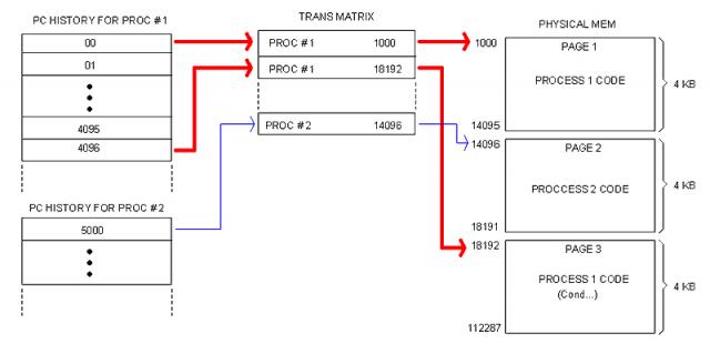
We have to distinguish between contiguous Linear address and contiguous Physical addresses. A code segment without branches, for instance, always occupies a contiguous block in the Linear domain but not necessarily in the Physical domain as illustrated in the following image.
This will possibly be a common scenario in real life. Notice that memory fragmentation is hidden to the program code (which is in Linear domain), meaning that System software working with these issues must work in the Physical domain instead. Hence the need for Physical-Domain instructions provided by the CPU.
Allocating Processes
When a process is loaded, memory is allocated to store the code and leave room for the process data. Since I am not providing support for a segmented model, both code and data will share a monolithic block in Linear space.
The upper portion (lowest addresses) contains the code; the data block follows and extends all the way down to the bottom of the designated space.
At loading time the Data block is only the space remaining in the last page occupied by the code. The process code is responsible for requesting memory to the OS is needed. The OS will allocate requested memory as contiguous as possible just below. This way, the space designated to the process will grow indefinitely only limited by the amount of physical memory available at allocation time.
The way processes utilize their data space is opt to the language Compiler. The OS and/or the CPU can help with support for different techniques (stack, heap, etc) but they won't dictate the way programming languages manage their data.
Linear Relative Address (RLA) and Program Counter (PC)
We have established that applications believe they own the entire Linear space. Such a believe is more than an illusion: actually, there is no other Linear space but that given to the application at run-time. We can see the Linear space as being "multi-dimensional": The Trans Matrix contains all its "dimensions": one for each application running at a given time.
It follows that applications supply only Linear addresses and those are not absolute but relative to the beginning of the designated block in memory. In other words, the CPU interprets addresses supplied by the application as offsets within the designated code-data block. We call this a "Relative Linear Address" (RLA).
Application code is linked to produce RLAs. The first RLA (where execution starts) is always cero. The address where the Data block starts (following the Code block) is known at Link-Time, so addresses for instructions such as "MOV A, ADDR" can be resolved by the Linker and they are also given as RLAs (relative to the beginning of the Code block).
This has implications to the Program Counter (PC).
Fetch bus cycles will perform address translation from a given a Linear address. But we just said that application code always starts in address cero. Since (at application run-time) there is no Linear space other than the one owned by the application, then the RLA becomes the actual address to be fetched. Therefore, the content of PC can't be other but the RLA provided by the application code.
When paging is enabled (that is, when not in Kernel mode) there is no need for a CS register. No need for a DS register either. I can still provide support for stacks (a SP reg and associated PUSH/POP instructions, for example) but that will be a plus, not strictly required by the conceptual model.
|