CPU Block DiagramThe computer is, in general, a synchronous machine governed by internal control signals. These signals control the behavior of individual registers, buffers, multiplexers and other circuits, in a timely basis.
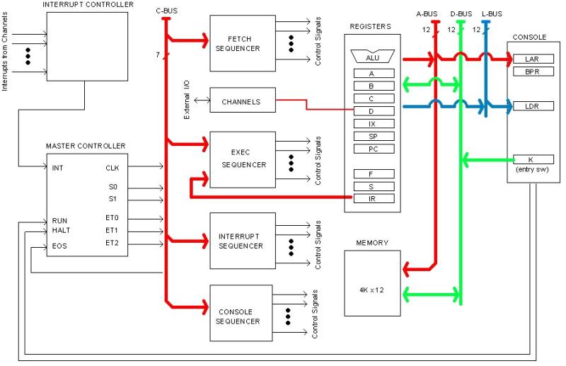
Below is a simplified block diagram of the CPU.
Registers and Memory communicate each other by the mean of an internal Data Bus (D-BUS), allowing transfer of data between then. The Console Entry Switches constitute a read-only register (K), also connected to the D-BUS.
The Address Bus (A-BUS) addresses the memory directly. Address is obtained from registers (indirect addressing) or directly from the instruction code (direct addressing).
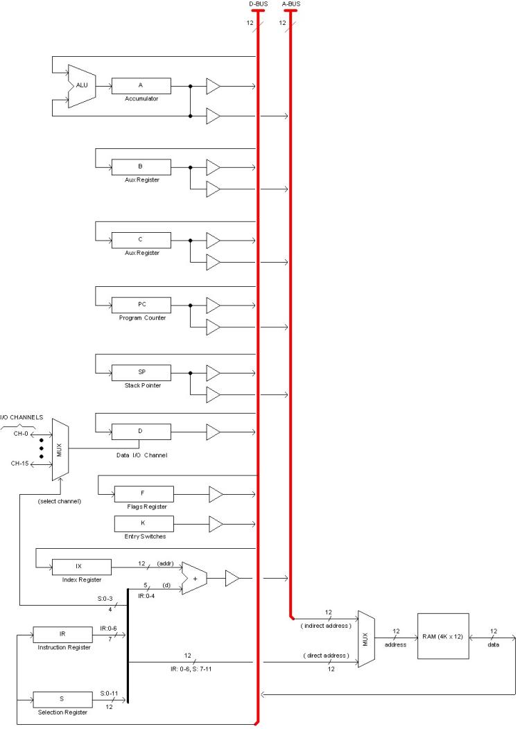
The following diagram shows the interconnection of registers and memory to the buses with more details.
A third bus, namely Lamps Bus (L-BUS) inputs the Console Lamps Data Register (LDR) in the console to present different register's content in the Console DATA Display. Selecting a register for view in the Console actually means outputting that register (or Memory) to the L-BUS.
All these registers and related circuitry operate governed by internal control signals generated by different "Sequencer" circuits. These, in turn, operate in sync with "master control signals" generated by the Master Controller and distributed in the Control Bus (C-BUS).
Sequencers and Master Control circuits are covered in details in section "Synchronization".
|