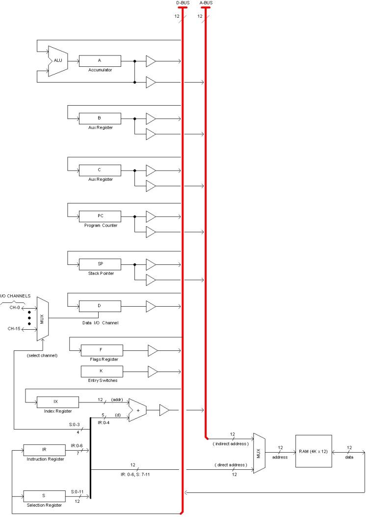
Registers and MemoryMemory is part of the CPU equipment. It is 4K x 12 bits, not extensible. Registers are implemented in the CPU equipment as well. The following diagram shows the CPU registers, the Memory, and how they connect to the Data (D-BUS) and Address (A-BUS) internal buses.
All registers are 12-bits.
The small triangles represent 3rd-state buffers isolating registers outputs from the buses. A typical register can output to both D-BUS and A-BUS; in the later case, the register is acting as a pointer to memory providing an "indirect address". Only one register can open to the same bus at the same time.
Register A acts as accumulator holding the result provided by the Arithmetic and Logical Unit (ALU), which is a combinational circuit capable of performing 16 different operations including 2's complement and BCD arithmetic. The default operation is "pass-through", in which case the accumulator functions as a general purpose register.
Auxiliary (general purpose) registers B, C and D are mostly intended to serve as pointers to memory although they can be used to hold temporary data as well.
PC, SP, IR and F are the Program Counter, Stack Pointer, Instruction register and Flags register, respectively.
Register K (read-only) is a direct input from the Console Entry Switches.
Register S holds the current channel number and the current memory page as explained later. In the diagram, S:7-11 contributes a "page number" to a 12-bits direct address, being the other 7 bits supplied by the instruction's code (IR:0-6). This is explained later in section "Paged Memory".
Index register (IX)
IX is the "index register". It provides an address with displacement intended for programs to access structured data in memory. The displacement is given by bits 0-4 of the instruction's code. Both numbers are summed out using an adder circuit to provide an effective 12-bits address IX+d as shown in the diagram.
Status Registers
Status registers (PC, F, S) define the current state of the machine as programs execute. That is why interrupts take care of saving PC, F and S content to the stack before branching so the machine state is preserved for the interrupted program upon return. The same is also true for CALL instructions.
Program Counter (PC)
When button RUN is pressed in the Console, the CPU starts a "Opcode Fetch Cycle". The memory cell which address is currently indicated by PC, is read into register IR. Then the instruction is decoded and executed, and the Program Counter is incremented appropriately.
Once the instruction is complete, a next Opcode Fetch Cycle is initiated and so on, until the machine is halted some how.
Flags register (F)
Flags bits indicate whether the last instruction resulted in a Carry (C), Zero value (Z), Negative value (N) or Overflow (V) in the target register. All ALU operations (except "pass-through") affects flags, as well as transfer and increment/decrement instructions. Writing to memory does not affect flags.
When pushed or popped to/from the Stack, the Flags register is treated as a monolithic 12-bit register, but its real implementation is different. For one part, only 8 bits are implemented (the 4 most significant bits always read zero). For the other part, flags need to be set/reset individually.
The register F also holds the current ALU function. This is latched as a result of ALU instructions having the LOCK keyword in assembly language (see section "SubClass 010: ALU" in "Instructions Set Architecture").
The following table shows the F register format:
bit designation descript
--------------------------------------------------------------------
0 f0 ALU function
1 f1 ...
2 f2 ...
3 f3 ...
4 V Overflow flag (result rolled-over to zero)
5 N Negative flag (most significant bit of result is 1)
6 Z Zero flag (all bits in result are zero)
7 C Carry flag (ALU result did not fit in 12 bits)
8 0 (not used)
9 0 (not used)
10 0 (not used)
11 0 (not used)
--------------------------------------------------------------------
Selection register (S)
The Selection register (S) holds the current memory page number (5 bits) and currently selected channel number (4 bits). The remaining 3 bits are not used and always read zero.
bit designation descript
------------------------------------
0 c0 channel number
1 c1 ...
2 c2 ...
3 c3 ...
4 p0 memory page
5 p1 ...
6 p2 ...
7 p3 ...
8 p4 ...
9 0 not used
10 0 not used
11 0 not used
-------------------------------------
Hidden registers
Hidden registers are those not accessible to the programmer in the sense that there no instructions to read or write them directly.
Register G
G is a name given to a collection of unrelated individual flip-flops:
FF Meaning when set
---------------------------------
IE interrupt is enabled
TE fail trap is enabled
Fail fault condition detected
----------------------------------
This register is cleared on reset, resulting in a halted machine with no pending conditions.
Lamps Address Register (LAR)
The LAR register latches the word being displayed in the Console ADDR display. Actually, those lamps are fed from LAR's outputs.
When the machine is halted, LAR provides the address to actually address the memory in operations such as examining and altering memory content.
During normal program execution, LAR is updated (latched) for each machine cycle.
Lamps Data Register (LDR)
Similar to LAR, the Lamps Data Register (LDR) holds the DATA display reading.
LDR register is fed from the Lamps Bus (L-BUS) which is fed in turn from the selected register or memory (M) as the operator selects so in the Console.
When the machine is in normal program execution, if M is selected, LDR is updated for each memory read or write cycle. If a register is selected instead, LDR remains open passing to the Display the L-BUS content (that is, the selected register).
When the machine is halted, LDR is the destination of memory reading cycles made by the Console circuitry when the Operator examines memory content.
Break Point Register (BPR)
The BPR register stores a break point set by the Operator.
When the BP/M switch is in its up position, BPR output feeds the ADDR display (instead of LAR). In this condition, BPR will latch the K register content (Entry Switches) if the SET button is pressed, being this the way for the Operator to set the Break Point in the machine.
Paged Memory
In order to provide direct addressing in a single-word instruction, the 4K memory space has been broken into 32 pages, 128 words each. The current page number is held in a 5-bits field of register S. The offset (7-bits) withing the page is encoded in the 12-bit instruction's op code.
This way, direct addressing instructions do not address the entire memory but only the current page. Another instruction allows to switch to the desired page. This apparent inconvenience can be camouflaged in assembly language with pseudo-instructions that accept 12-bits addresses to automatically insert a page-switch instruction if necessary.
In the diagram, we can see how bits from registers S and IR are combined to build the 12-bits direct address.
|