Search   
Home  Print View  


Architecture

Table of Content

This section describes the computer's hardware in a generic, introductory way.
The Instructions Set Architecture (ISA) is covered in details.


Click to selectGeneral description
HER/12 is a parallel registers-based 12-bit mini-computer built from discrete Small and Middle Scale of Integration (SMI, MSI) integrated circuits of the 7400 series. It does not employ LSI components other than semiconductor Random Access Memory (RAM) chips.

The machine consists of the CPU equipment and up to 16 external peripherals connected to the CPU via I/O channels (as opposite of external bus).

The CPU contains the main memory, organized in 4096 words of 12 bits each. Memory expansion is possible through RAM-DISK peripherals connected to channels. RAM-DISKs are block devices with maximum capacity of 256 Mwords.

Other peripherals could be: printers, punch tapes, magnetic tapes, serial ports, D/A and A/D, GPIO, real-time Timers and many others.

The CPU is operated by the mean of a Console located in the front of the CPU. Software and data can be entered into memory either manually (using the Console) or from external support such as punch tape or magnetic tape.


Click to selectRegisters and Memory
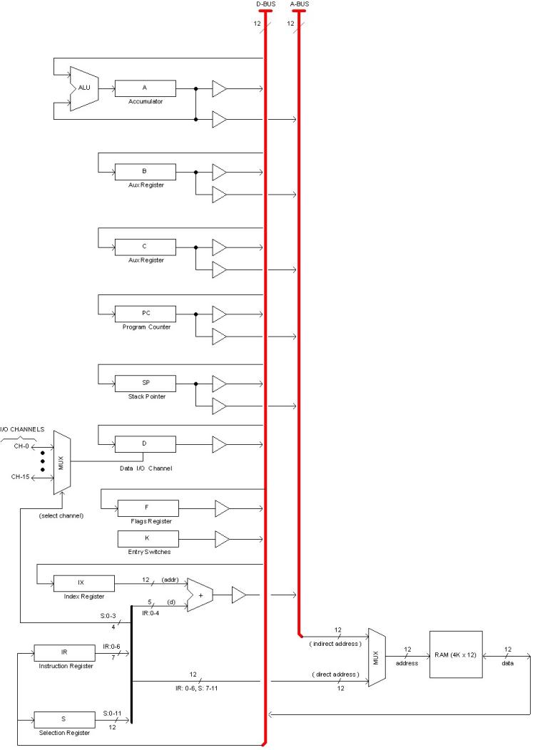
Memory is part of the CPU equipment. It is 4K x 12 bits, not extensible. Registers are implemented in the CPU equipment as well. The following diagram shows the CPU registers, the Memory, and how they connect to the Data (D-BUS) and Address (A-BUS) internal buses.


All registers are 12-bits.

The small triangles represent 3rd-state buffers isolating registers outputs from the buses. A typical register can output to both D-BUS and A-BUS; in the later case, the register is acting as a pointer to memory providing an "indirect address". Only one register can open to the same bus at the same time.

Register A acts as accumulator holding the result provided by the Arithmetic and Logical Unit (ALU), which is a combinational  circuit capable of performing 16 different operations including 2's complement and BCD arithmetic. The default operation is "pass-through", in which case the accumulator functions as a general purpose register.

Auxiliary (general purpose) registers B, C and D are mostly intended to serve as pointers to memory although they can be used to hold temporary data as well.

PC, SP, IR and F are the Program Counter, Stack Pointer, Instruction register and Flags register, respectively.

Register K (read-only) is a direct input from the Console Entry Switches.

Register S holds the current channel number and the current memory page as explained later. In the diagram, S:7-11 contributes a "page number" to a 12-bits direct address, being the other 7 bits supplied by the instruction's code (IR:0-6). This is explained later in section "Paged Memory".


Click to selectI/O Architecture
Every peripherals connects to the CPU by the mean of a circuit called "Channel". The term has been borrowed from early IBM main frames, only that those were based on smaller dedicated computers (such as IBM 1401) whereas HER/12 channels solely provides a connection between the peripheral and the CPU buses, with no intelligence at all.

Up to 16 channels are supported but only one can connect to the CPU buses at a given time; that is said to be the "selected" channel. Selection can be made by software during normal program execution or manually by the mean of the Console when the computer is halted.

Data transfer is always between the selected channel and memory, using indirect addressing. The channel never reads or writes directly to a register.

Communication with peripherals is always initiated from the CPU. Peripherals can, at the most, assert interrupt signals to get CPU attention.
Powered by HelpBooks version 0.86, running at: melissa