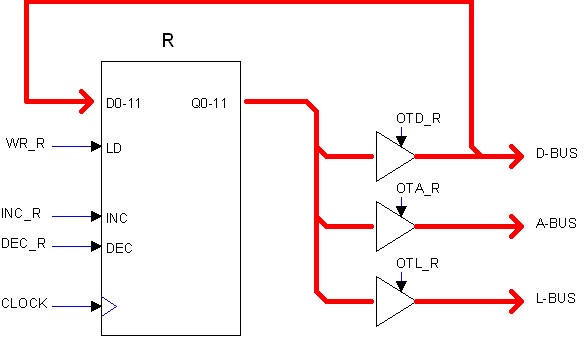
Registers implementationMost registers in the HER/12 are implemented using Synchronous Presetable up/down 12-bits counters (actually a combination of three 4-bits ICs). This implies the following:
* Registers can be load in paralell from the D-BUS.
* They can be incremented or decremented without ALU intervention.
* Either load or inc/dec operations occurr in sync with the computer's master clock. That is,
once the proper signals are applied (such as INC), the actual operation does not occur until
the next falling edge of the clock in the middle of the period, takes place.
Counters outputs are isolated from the buses by the mean of 3-state buffers. These buffers are considered part of the register's circuit and they are the following:
* Buffer to the A-BUS (internal address bus)
* Buffer to the D-BUS (internal data bus)
* Buffer to the L-BUS (internal lamps bus)
This last lead to the Console's LDR register to be shown in the DATA Display when the Operator selects that register in the Console.
Control signals related to registers are the following (using hypothetical register R):
OTA_R Output To Address: Open the buffer to A-BUS (indirect address)
OTD_R Output To Data: Open the buffer to D-BUS
OTL_R Output To Lamps: Open the buffer to L-BUS
WR_R Latch D-BUS content into register
INC_R Increment register content
DEC_R Decrement register content
OT? signals are asynchronous. WR, INC, DEC are synchronous and must be applied ahead of time (for example, at the beginning of the clock period) to be executed with the next falling edge of the clock master clock.
Operation WR_R takes priority over INC_R or DEC_R.
|