Control SlotsFor Control Slots, same control pins plus the 16 address lines (not used by IDS cards) are wired in three local control buses: C-BUS, S-BUS and T-BUS. Lines D0-15 are not wired from the internal Data Bus as in Data Slots but directly from the Instruction Register (IR).
The table below shows the pin out for Control Slots.
A B C
- - - - - - - - - - - -
1 DO SF D8
2 D1 SR D9
3 D2 S0 D10
4 D3 S1 D11
5 D4 CSZ D12
6 D5 CSN D13
7 D6 CSC D14
8 D7 CS3 D15
9 GND CS4 GND
10 CLK CS5 IE
11 GND CS6 CTL
12 ET0 CS7 CTL
13 ET1 CCS CTL
14 ET2 CTL CTL
15 GND CTL CTL
16 CTL CTL CTL
17 GND CTL CTL
18 CTL CTL CTL
19 GND CTL CTL
20 CTL GND CTL
21 CTL CTL CTL
22 CTL CTL CTL
23 CTL GND CTL
24 CTL CTL CTL
25 CTL CTL CTL
26 CTL CTL CTL
27 CTL CTL CTL
28 CTL CTL CTL
29 CTL CTL CTL
30 CTL CTL CTL
31 CTL CTL CTL
32 +5V +5V +5V
Control Bus (C-BUS)
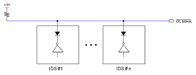
The purpose of wiring all control signals in a bus is to allow different controllers (such as IDSs and the Interrupt Controller) to manage the same control lines as illustrated in the figure below:
Status Bus (S-BUS)
SF Fetch Cycle
SR System Reset
S0 Operational Status
S1 Operational Status
CSZ Conditional Status Zero
CSN Conditional Status Negative
CSC Conditional Status Carry
CS3 Conditional Status (Reserved)
CS4 Conditional Status (Reserved)
CS5 Conditional Status (Reserved)
CS6 Conditional Status (Reserved)
CS7 Conditional Status (Reserved)
CCS Clear Conditonal Status
IE Interrupt Enabled
SF signal is activated by instruction decoding logic (located at IDS cards) during the falling edge
of the last clock cycle of every instruction. The signal is used to syncrhonically clear both IR and the T-Counter; this action forces an Op Code Fetch Cycle taking place with the next clock rising edge.
S0, S1 define the current Operational Status according to the following table:
- - - - - - - - - - - - - - - - - - - - - - - - - - - - - - -
S1 S0 Operational Status
- - - - - - - - - - - - - - - - - - - - - - - - - - - - - - -
0 0 Halt
0 1 Interrupt being negotiated (before ISR is called)
1 0 IDS having control in Step mode
1 1 IDS having control in Run mode
- - - - - - - - - - - - - - - - - - - - - - - - - - - - - - -
If S1=0, IDS card ihibit themselves so other circuit (such as the Interrupt Controller or the Console) can take control of the machine. When S1=S0=1 and interrupt is enabled (IE=0), the Interrupt Controller card is allowed to serve interrupts. In that event, the Interrupt Controller will pull signal S1 down to zero for inhibiting IDS cards so it can take control of the machine while negotiating the interrupt with the interrupter device (see Interrupt life-time).
Conditional Status signals come from the Flags Registers (F). The first three are defined: CSZ, CSN, CSC; the other five (CS3-7) are reserved for future use. These signals are set from data oriented circuits; for instance, a register been cleared by an instruction will activate the CSZ signal). The signal CCS (activated by a controller such as an IDS card) will clear all flags at once.
Sequence Bus (T-BUS)
The T-BUS is fed from the "Sequece Counter" and represent the encoded clock cycles: T1, T2, ... T6. Actual signals are termed "ETi" for "encoded time":
ET0
ET1
ET2
Note: ET0 = ET1 = ET2 = 0 represents T1.
|