Second approach to implementation05/26/2009
In this second try, I'm bassically scalling down the first to manageable values.
Critics to my first approach
My "First approach to implementation" failed to meet expectations. Here is why.
32 bits architecture
There is no need for a 32 bits architecture. The aim of 32 bits address space with 32 bits data path was only in to leave enough room for further development. However, the figures ran close to unfeasibility so I've decided to restrict the architecture down to reality. After all, it is not my plan to compete with my PC but just to create a hardware environment to play with.
The all-for-one commitment policy with 32 bits
I have adhered to this principle from the very beginning. It stated that every application running in protected mode must believe it owns the entire Linear address space, that is all memory in the system (and yet that not physically present) up to 4GB (2^32).
I still consider it's a good idea. Problem is that 32 bits are too many bits. That, combined with the multi-dimensional Trans Matrix, ran out of reality big time.
Code and Data in monolithic block
Putting code and data together in same block under the application's control makes it difficult to share process's images among different users.
In a multi-user environment same process should be able to run on behalf of different users at the same time, so the process's code must be shared among them but the data must not. It follows that it's better to keep code and data in separate areas perfectly distinguishable by the Operating System for easier manipulation.
Brief description of the "new machine"
Here is how the machine starts to looks like:
Data Bus : 16 bits
Address Buss : 24 bits
Main Memory : SRAM up to 16 MB
Virtual Linear Space : From 0 to 2^24 - 1
Paging mechanism : 128Kx16 SRAM Translation Matrix not in Addr Space.
Max symultaneous processes : 32
All-for-One Policy
As stated before, the System commits all Linear address space to each application running at a given time. User applications are linked to produce Linear Addresses relative to the beginning of the designated code block, starting with address cero. Maximun address is 2^24 - 1.
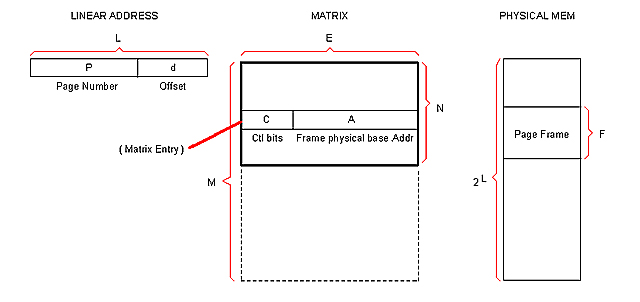
Linear Address and Paging
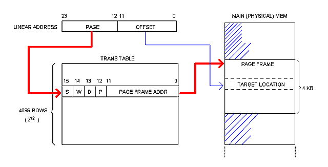
A Linear address is 24 bits wide. It is broken into two 12 bits fields: PAGE and OFFSET.
Physical memory is broken into 4 KB blocks of contiguous addresses called "Page Frames". The page frame constitutes the memory allocation unit.
Each page frame is described (and translated) by the corresponding entry (or "Frame") in the Trans Table, as illustrated bellow.
Each process processes its own Trans Table. System Software (OS) is responsible for keeping them updated at boot-up and run-time.
Multi-dimensional Trans Matrix
Trans Tables are not in Main memory but in a separate circuit called "Trans Matrix" (or simply "Matrix") which is 16 bits wide and 128K rows deep regardless the amount of physical memory installed in the machine.
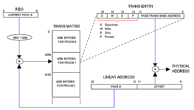
The Matrix is said to be "multi-dimensional" because it contains the Trans Tables for all 32 allowed processes. This way, each process runs in its own "dimension" of the Linear space. The OS distributes physical memory among processes dynamically by filling in the Matrix.
The following diagram illustrates how it works.
( + ) and (REG * 4096) circles are shown for illustrative purposes only. In practice REG will simply contribute the most significant bits to the Matrix row decoder whereas the PAGE field of the Linear address will contribute the least significant ones. Same for: PAGE FRAME BASE ADDRESS + OFFSET = PHYSICAL ADDRESS.
Super-Linear space
Unlike user processes, that always work in Linear space (within its own "dimension"), Kernel code needs access to all processes memory meaning that it needs access to the whole Trans Matrix.
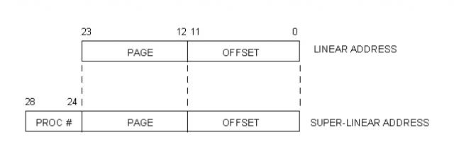
With this purpose, we define a "Super-Linear Space" that ranges from cero to the size of the Trans Matrix times the size of a page frame.
Using the limits we have established, the size of the Super-Linear Space can be calculated like this:
SL_Size = (Page_Frame) (Trans_Table_Entries_per_Process) (Max_Processes)
= (4KB) (4096) (32)
= (2^12) (2^12) (2^5)
= 2^29
= 512 M
The following diagram illustrates the relationship between Linear and Super-Linear address.
Paging in Kernel mode
05/27/2009
Since Trans Tables are not in Main memory, there is no need for defeating Paging when Kernel code is running. Moreover, keeping Paging active brings advantages to the Kernel's job.
Let's assume that the Trans Matrix has been pre-initiated by some pre-Kernel software possibly hold in ROM chips. This initiation regards only the first Trans Table: that of the Kernel. Yes, Kernel code resides in virtual space so it suffers address translation as everyone else. Kernel is nothing but "Process #0".
There is something special about this Kernel area, however: The CPU is designed so all interrupts are serviced from Trans Table #0, that is Process #0 which is the Kernel.
This has implications to System Calls.
When a process needs Kernel attention, it raises INT 80 (the number 80 is just an example, matching Linux in this case). Call arguments are passed in CPU registers, as expected.
In some cases, arguments represent pointers to memory (a buffer, a stru file descriptor, etc). The question is what kind of "memory address" does this pointer represent: a Physical address or a Linear Address?
We have established that processes only deal with Linear addresses so that is the only kind of address it can pass in a System Call. The Kernel code would then have to make a translation (to physical address) based on information it holds about the calling process.
With Paging enabled, the translation is almost automatic.
Say for instance that the calling process has passed a buffer's address where it wants data to be placed. This will be a Linear address pointing (relative) to somewhere within the process's data block. Let's call it LOCAL_BUFF.
In order to know where to serve the requested data, the Kernel needs to compute a "Super Linear Address" which translation matches the physical address of LOCAL_BUFF. Let's call it BUFF and calculate it like this:
BUFF = (PROC# * 4096) + LOCAL_BUFF
Now, by simply addressing the Matrix with BUFF, the exact Physical address is automatically obtained. In other words, the user's buffer has been addressed via ordinary bus cycle with Paging enabled.
We see that "Kernel mode" is not a strong concept any more; Kernel pages are marked as Supervisor which allows access to special CPU instructions, that's all. We see also that Paging does not need to be enabled or disabled; all buss cycles can be done in the same way by using the Matrix.
One may argue that the Kernel will need to fill in the Matrix any ways with physical addresses so it must be able to work in the Physical domain. One answer may be that the Matrix is only accessible through special supervisor instructions since it is not in addressable space; thus Kernel code could manage to know the Physical memory without having to actually address it; as a matter of fact the Matrix maps the Physical Memory in some way.
I can't have this as a final conclusion, however. For one part, that is not the way real-life Kernels and processors work; for the other, I haven't explored all of the consequences with full detail. Moreover, being this an "experimental" computer, it is better for me to have as many choices as possible, as for instance the ability to enable/disable the Paging mechanism.
Addressing the Matrix
05/28/2009
I were thinking of a set of privileged instructions as the only way to access the Matrix. But now it occurred to me that a more open (so powerful) mean would be to allow Kernel code to simply address the Matrix.
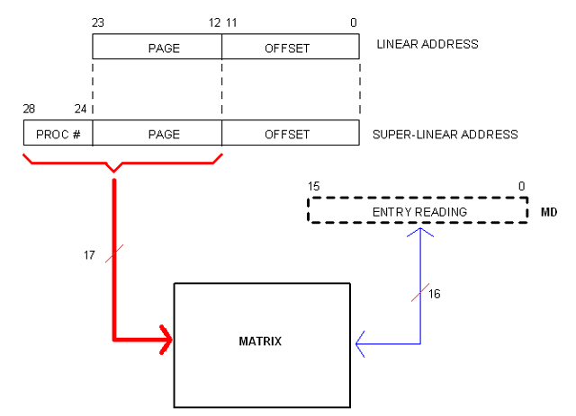
Of course, Kernel code will be doing so in Super-Linear space. However, only the most significant 17 bits of the (29 bits) Super-Linear address are needed since the other 12 represent the off-set within the page frame (as in Matrix entries). The following diagram illustrates the idea.
Register MD is not a real one but a fictitious resource provided by the CPU to facilitate Matrix Read/Write operations as in (for example):
MOVI MD, value
CPU the first Sketch
05/29/2009
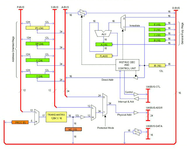
The following drawing is an early sketch (actually the first) of the CPU architecture or block diagram, whatever you want to call it.
This is supposed to be a single PCB card. As per today I don't know if the computer will take one or more units (enclosures); several cards, for sure. The idea is that all cards (and/or units) will be plugged to a common bus that I have called UNIBUS (as that of the legendary PDP-11, not sure if I'm going to adopt exactly that bus).
The UNIBUS consist of Data lines (16), Address lines (24) and Control lines including IRQs. In the drawing they are termed: UNIBUS-DATA, UNIBUS-ADDR and UNIBUS-CTL respectively. This is the way out for the unit (or Card).
There are also internal buses. Those are: D-BUS (16 bits Data), A-BUS (24 bits Address), X-BUS (12 bits Offset) and P-BUS (12 bits Page). These buses communicate registers and other resources inside the CPU card.
Registers can be classified into three categories:
- General Purpose: A, B, C, D, E
- Address Oriented: PC, SP, X, Y
- CPU specific: IR, FLAGS, PROC, MD
There is also the Trans Matrix.
General Purpose registers are 16 bits and they are accessible to the applications programmer. The Accumulator (A) serves as left operand and result holder for the ALU (as in must real-life processors).
Address Oriented registers are 24 bits. They have bidirectional access to the A-BUS and split one-way access to the P-BUS and the X-BUS. In the drawing, each line is marked with the number of bits it carries; when split, an H or L suffix added to the number indicates whether it is the Most or Least significant half.
CPU specific registers have different sizes. IR (16 bits) is the Instruction register; FLAGS is the Status register. When the CPU is in Protected mode, the register PROC (5 bits) indicates the current process number. MD is a fictitious register that represents the current Matrix entry.
The Matrix is a SRAM arrangement of 128K rows by 16 bits. It is addressed by the combination (multiplex) of PROC and the P-BUS. The 12 least significant bits of the selected row represents the physical base address of the Page Frame to be addressed in the current bus cycle. By multiplexing this output with X-BUS (which contributes the Offset) the whole 24 physical address is obtained. If the CPU is in Protected mode, that address is taken to UNIBUS-ADDR; otherwise, the A-BUS content is taken instead.
In the drawing, registers are marked with different colors to highlight privileged use. Green registers are accessible to the Applications programmer. Orange registers are only accessible to System programmers (that is, if the CPU is in Protected mode, code cannot access these registers if it is not in page frames flagged as "Supervisor"). Yellow registers are indirectly accessible throughout instructions; for example, a jump instructions overwrites the Program Counter. When the CPU is in Real mode, page priviledges are not checked so orange registers are accessible to all code.
Note that register PROC is for System programmers use. That is the way for Kernel code to work in Super-Linear space (I'm keeping my idea of the Kernel working in Protected mode but this may change).
Some implementation details are not clearly illustrated in the drawing as for example the rules for transferring data between registers of different sizes. There is a number of different ways of doing that but I'm not going to work it out at this time.
Calculating the Matrix
The size (thus the cost) of the Matrix has proven to be a critical concern. Lets imagine a generic Matrix so we can adjust values until acceptable results are obtained.
These are the variables:
L : Size of the Linear addressable space.
P : Size of the PAGE field in the Linear address.
d : Size of the OFFSET field in the Linear address.
F : Number of addresses composing a Page Frame in physical memory
E : Size of a Matrix entry.
A : Size of the FRAME_ADDRESS field in the Matrix entry.
N : Number of Matrix entries per Table (that is, per process).
S : Number of max simultaneous processes.
M : Total number of Matrix entries (for S processes).
Note: Sizes are in bits.
Here are the relationships between those variables:
d = log2 (F) ; Number of bits needed to address F
P = L - d ; A linear address has L bits
A = P ; This conclusion is easy to obtain
N = 2^P ; The Trans Table has as many entries as P can address
M = N * S : The Matrix has as many tables as allowed sim. processes.
Procedure
We start by fixing the size of the Linear space (L) since that will determine the max amount of physical memory allowed in the system.
Then we fix the size of the page frames (F). Here is a trade-off situation: The smaller is F, the bigger becomes the Matrix; but making F too big will degrade memory management efficiency. We can start with a reasonable value (say, 4KB).
With these two variable fixed, we can start doing the math
#Linear Address fields:
d = log2 (F) ; Number of bits in the OFF_SET field
P = L - d ; Number of bits in the PAGE field
#Matrix entry:
A = P ; Number of bits in the FRAME_ADDRESS field.
The Matrix entry also has control bits (about 4) and can also contain reserved bits. What we do is to add them all, then we round to a multiple of 4 (for practical reasons). Extra bits resulting of rounding will be considered "reserved".
#Trans Table size:
Trans Table is the chunk of Matrix dedicated to one process. The number of entries is:
N = 2^P
So far we have a Matrix that is N rows by A bits... per process.
#Matrix size:
The Matrix has as many trans tables as simultaneous processes are allowed (S). This is another trade-off situation. In this step we fix S seeking a comfortable value with acceptable cost in Matrix RAM.
M = N * S
The final size of the Matrix is M rows by A bits.
Example
Let Main Memory be 2MB as the most. Therefore L = 21.
With such a small memory lets keep granularity high, say 1 KB per frame, that is: F = 1024.
#Linear Address fields:
d = log2 (F) = 10
P = L - d = 21 - 10 = 11
#Matrix entry:
A = P = 11
We have 4 control bits so the entry would be: 11 + 4 = 15 bits. Since this is kind of odd, we round to 16 bits and tell programmers we have let a "reserved bit", which sounds very technical.
#Trans Table size:
N = 2^P = 2048
So we have 2K x 16 bits (4KB) per process.
#Matrix size:
Let say we want to allow up to 128 simultaneous processes.
M = N * S = 2048 * 128 = 262,144
That is 256 Kwords (512 KB).
If we can afford to build this Matrix, then our system can be described as following:
- Main memory : 2 MB max
- Sim. Processes : 128 max
- Matrix size : 256K x 16 bits (512 KB).
(not too bad...)
|