ContentThis section describes the computer's hardware in great details including theory of operation and schematics of the different LC-81 units.
Master Controller Unit (MC)
The mission of the MC is to provide the intelligence to the system. This unit contains the microprocessor (Zilog Z80), the first 24 KB of memory (8KB EPROM + 16KB RAM), and logic for coordinating INT and DMA requests asserted by external devices throughout the EXT-BUS.
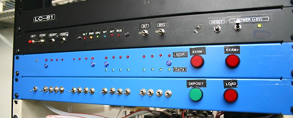
A DSUB-37 connector is present in the rear to expose the EXT-BUS being this the only way out for the MC. In the front, a "traditional" Control Panel (Console) is offered to the Operator for machine control and software debugging.
Operational Modes
The LC-81 minicomputer operates in two distinct modes: Halt and Run.
After power-on or reset, the machine falls into HALT mode. This is accomplished by asserting a BUSREQ to the microprocessor. Since the Console Controller does not depend on software to operate (except for the START button) it can take control of the buses (both internal and external) so this is the time for the Operator to make use of the Console for inspecting/changing memory content (both private and external) as well as peripheral registers.
Pressing the START or CONT button causes the machine to enter RUN mode. This is accomplished by removing the BUSREQ to the microprocessor so it can resume execution. The Operator can stop the machine at any further time by pressing the HLT button which causes the machine to enter HALT mode again.
STEP execution is also supported. This is accomplished by synchronizing with the microprocessor signal M1 which activates at the beginning of each Opcode Fetch cycle.
Private Memory
The memory contained into the MC is said to be "private" because it is isolated from the EXT-BUS by the mean of 3rd-state buffers so no external device can gain access to it in any way.
It is possible to build an external Memory Unit to provide "shared" memory. That would be the one used by DMA capable peripherals.
The use of a separate private memory allows for concurrent operations between DMA operations and normal software execution as long as this takes place in private memory.
EXT-BUS Gating
All EXT-BUS lines are behind 3rd state buffers in the MC unit. A "gating" logic is implemented in order to isolate external DMA transactions from Software running in MC private memory (internal buses) so they can take place concurrently. The logic is as following:
The bus is normally "closed" (high impedance state). In this conditions the Microprocessor access private memory and the Console register SAR (I/O address: 01 and 02). If the Microprocessor attempts to access external memory (address beyond 5FFFH) or I/O other than 01 and 02, the bus "opens", the signal BSY is activated in the bus to indicate that condition, and the lamp "BUS" is illuminated in the MC front panel.
A DMA capable peripheral requests bus control by raising the signal BRQ. In presence of this signal, the Bus Gating circuits closes the bus immediately (if it was not closed already). If the Microprocessor attempts to access external memory or I/O, a wait signal is asserted so the Microprocessor waits until the BRQ is dropped. The BSY signal however is not dropped. The operator can recognize this situation because lamps "BUS" and "WT" in the front panel are both illuminated.
Application programs are expected to run in Private Memory utilizing buffers located in External Memory shared with DMA peripherals. Access to those external buffers is negotiated with DMA as explained and the terms of the negotiation favors DMA in order to ensure the success of those (possibly critical) transactions.
DMA peripherals are expected to monitor the BSY signal, not to assert BRQ is it is active, and not to monopolize the bus for a long period of time.
MC Electronics
The MC electronics resides in three separate boards called respectively: CPU board, Console Registers and Console Controller. The first contains the microprocessor, memory, EXT-BUS 3rd-state buffers and logic. The other two supports the Console's functionality.
Console's buttons, switches and "lamps" (actually LEDs) are located within the assembly mounted on PCBs but no electronics other than LED buffers exists outside the three boards mentioned before.
Console Electronics
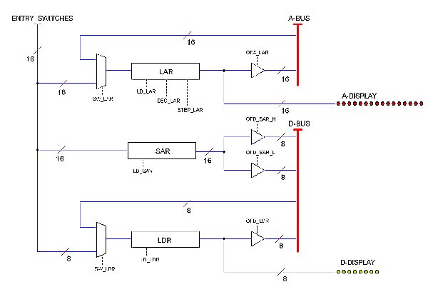
The Console works independently (with no software support, except for the START operation), based in its own logic implemented with discrete TTL components. The circuit is broken into two boards: the Console Controller board and the Console Registers board. The later contains the console's registers, buffers and multiplexers as shown in the block diagram below. The former provides the necessary control signals sequences to manage those resources according to a logic triggered by the buttons and switches available to the operator in the front panel.
In the diagram, A-BUS and D-BUS represent the MC internal Address and Data bus respectively. All control signals (SW_LAR, LD_LAR etc.) are provided by the Console Controller board.
Register LAR (Lamps Address Register) holds the address being presented by the Address lamps. A 3rd-state buffer isolates this output from the A-BUS; control signal OTA_LAR (Output To Address) causes the buffer to open so the content is available in the A-BUS. The input may come from two different sources depending of the state of the preceding Multiplexor: that may be the Entry Switches or the A-BUS; signal SW_LAR determines the Multiplexor state: when active, the Multiplexor switches to A-BUS.
Signal LD_LAR (Load) makes the register to latch the input. Signal STEP_LAR causes the register to increment or decrement its content depending or DEC_LAR being inactive or active respectively.
Register LDR (Lamps Data Register) holds the content being presented by the Data lamps. The input may come from either the Entry Switches or the D-BUS. Buffered output goes to the D-BUS. Control signals SW_LDR, LD_LDR and OTD_LDR (Output to Data) have similar meanings as those in the LAR register. The LDR register, however cannot be incremented or decremented, only latched.
The register SAR (Start Address Register) holds the starting address for the program to be run when the operator presses the START button. Its 16 bits content is read by the Microprocessor into its PC register during a NMI interrupt asserted by the CPU board when the START button is pressed. This takes two reading operations: one for the LSB, other for the MSB, hence two buffers are necessary, triggered by control signals OTD_SAR_L and OTD_SAR_H respectively. These signals are generated by the Console Controller board when I/O ports 01H and 02H (respectively) are addressed by the Microprocessor.
When the operator presses the LOAD button, the status of the Entry Switches is latched in both registers LAR and SAR (signals LD_LAR, LD_SAR). The resulting memory address is read into LDR making the new content visible to the operator in the Data lamps.
When the operator presses the EXAMINE+ or EXAMINE- button, LAR is incremented (or decremented) and the resulting memory address is read into LDR.
Pressing the DEPOSIT button causes LDR to latch the Entry Switches state and that to be written into the memory location (or I/O device) addressed by LAR at that moment. LAR is automatically incremented and the resulting memory location (or I/O) is read again into LDR.
Control Signal sequences to allow all this to happen are built in the Console Controller board by the mean of a diodes matrix. Diodes are pluggable to allow further adjustments in the "microcode" if ever that would be needed.
Schematics
 CPU board CPU board
Console Display board
Console Registers board
Console Controller board
EXT-BUS pinout
Open-Reel Tape Drive
A professional open-reel 1/4 inches Stereo Audio Tape Recorder OTARI MX-5050, without modifications, will be utilized as data Tape Drive for the LC-81 minicomputer. A controller equipment (namely "Tape Controller") will serve as interface between the two. The Controller will connect to the LC-81 via EXT-BUS, and it connects to the OTARI via audio cables and a special control cable.
The OTARI MX-5050 is very generous in terms of control. It offers a DB37 connector in the rear, labeled "Parallel I/O", with GPIOs for asserting and tallying virtually all machine operations such as Play, Record, Rewind, etc. Also in the Parallel I/O connector is a 9.6 KHz reference pulse and also the output of the Tachometer (120 pulses per second at nominal speed).
The resulting equipment will be a Tape Drive entirely controlled by software running at the LC-81 and complaint with the LC-81 Tape Drive Specification (see section "Specs").
Encoding
Data and Clock are recorded in separate tracks at 9600 bits per second. No modulation is used, data is written in base binary format at TTL levels.
The 9.6 KHz clock is utilized to encode and decode bits by the mean of a UART chip 16C550. The byte format (programmed in the chip) is: 8 data bits, 1 stop bit, no parity.
Data is expected to be grouped into blocks separated by gaps. The length of a block is determined by the software making use of the drive, expected in the order of one to a few kilobytes.
Gaps are defined in the clock track. Within gap areas, the clock is 1.2 KHz instead of 9.6 KHz. No-file areas (for example, all tape long after the last block) is distinguible because of the absence of pulses in the clock track.
The use of separate tracks for clock and data and the non use of modulation presents the following advantages:
* High tolerance to variations in tape speed (Wow and flutter)
* About ten times the bit rate as compared to modulated encoding.
Development Notes
 Experimentation Experimentation
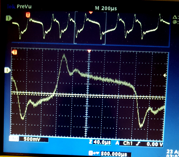
Recording a data file via RS232
Recording direcly from DOSILA serial port with RC decopling in between (1K, 0.1 uF), a large file (JOURNAL.TXT) was dumped. Here is the playback reading:
The problem of appending data to the end of the tape
Los tapes que estoy usando pueden almacenar cerca de 1 MB de data. Obviamente no voy a llenarlos de un tiron sino en varias sesiones de trabajo. Esto implica la necidad de operaciones "append".
Se supone que el tape se escribe en bloques separados por GAPs; estos ultimos se definen por ausencia de reloj en el segundo track... o tal vez por un reloj de diferente frequencia (digamos, 1KHz).
Se supone tambien que el final del file se marca con un caracter EOT. Hacer "append" significa sobre-escribir la marca EOT con data y continuar escribiendo hasta el final del bloque como se la marca EOT nunca hubiera estado alli.
El bloque que contiene EOT, en general no esta completo; el resto del bloque, o bien se deja limpio pero se sigue rellenando con reloj en el otro track, o bien se trunca haciendo un GAP a continuacion en cuyo caso el ultimo bloque siempre (o casi siempre) seria mas corto que el resto. Esto ultimo me parece mas razonable puesto que ese remanente de bloque vacio carece de utilidad y puede estorbarme en terminos de eficiencia.
En cualquier caso, para hacer append tengo primero que encontrar el final del file. Esto implica otra operacion que pudieramos llamar: "seek" (en general) or "seek EOT" (en particular).
Como hariamos?
La solucion mas simple (y menos eficiente) es poner el tape en PLAY desde el inicio para hacer una busqueda secuencial de EOT. Eventualmente lo encuentro y dentengo la cinta... y he aqui otro detalle: la cinta no se debe detener sino en un GAP. Si he optado por bloques truncados, una vez encontrado EOT me detengo pues el GAP esta ahi mismo a continuacion; si no, dejo correr la cinta hasta el proximo GAP, es decir, por el resto de ese ultimo bloque... he aqui como optar por bloques completos conspira contra la eficiencia.
En cualquier caso, ahora estoy detenido en un GAP y la marca EOT esta "detras de mi". Para alcanzarla (sobre-escribirla) tengo que rebobinar... porque otra regla ha de tenerse en cuenta: no se puede escribir en medio de un bloque; para editar o completar un bloque hay que sobre-escribir el bloque en su totalidad.
Asi que ahora tengo que encontrar el principio de ese bloque y leerlo enteramente en memoria (incluida la marca EOT). Para encontrarlo, debo rebobinar hacia atras (RWD) pero solo un corto tramo. Aqui cabe implementar esa operacion en el Tape Drive: Step-Rwd, que significa rebobinar hacia atras un bloque aproximadamente.
La operacion Step-Rwd me conduce a algun lugar intermedio del bloque anterior, es decir, poco antes del GAP que antece al bloque que contienen el EOT. Una vez finalizada esta operacion, hago una operacion normal de lectura.
La lectura debe hacer lo siguiente: Dejar correr la cinta en PLAY sin hacer nada hasta encontrar un GAP, dejar pasar el GAP y comenzar a leer a partir de alli. Asi que en este momento estoy leyendo todo mi bloque en memoria (buffer).
Una vez buffereado el bloque (estoy hablando del ultimo bloque del file, ese que contiene en EOT), lo edito en memoria, es decir, el "append" se hace primero en memoria sobre-escribiendo, como hemos dicho, la marca EOT con el primer byte de data a escribir. Y una vez completado el bloque en memoria, lo escribo en cinta... pero cuidado! -> Hay que rebobinar la cinta otra vez para encontrar el inicio de ese bloque. Esto se hace mediante una operacion Step-Rwd, luego de lo cual se hace una operacion de escritura. Esta ultima es similar a la de escritura: Se deja correr el transporte en PLAY sin hacer nada hasta encontrar un GAP, se deja pasar el GAP y luego se escribe a partir de alli hasta completar el bloque.
Refinamiento
La operacion "Seek EOT" debe bufferar cada bloque en memoria sobre-escribiendo el buffer cada vez, de modo que una vez encontrada la marca EOT no haya necesidad de rebobinar para voler a leer el bloque. La operacion Step-Rwd sigue haciendo falta porque una vez editado el bloque en memoria hay sobre-escribirlo en tape.
Se puede evitar tener que correr la cinta en PLAY desde el inicio si se implementan operaciones "Step-Fwd" (and possibly) "Far-Step-Fwd" con el fin de posicionar la cinta en un punto cercano al buscado. En general, hay que disennar una serie de operaciones que permitan economizar tiempo en las operaciones de busqueda.
Seria formidable que el Drive fuese capaz de detectar la presencia de GAPs durante el rebobinado (de ahi la idea de usar tonos de baja frecuencia en lugar de no-clock). De ser asi, pudieran implementarse operaciones "seek" capaces de contar bloques para atras y para alante. Esto queda pendiente de experimentacion.
Conclusion
El GAP no puede ser ausencia de reloj ya que en tal caso la region virgen de la cinta (mas alla del ultimo bloque) pudiera confundirse con un GAP. El GAP debe consistir en un tono de baja frecuiencia (posiblemente 1 KHz) en el track del reloj (que es 9.6 KHz).
Siempre observar las siguientes reglas:
* La cinta nunca se detiene sino es sobre un GAP
* La cinta nunca comienza a escribirse ni leerse sino es despues de detectado
el GAP de comienzo de bloque.
Para poder detecat el GAP correctamente, la cinta ha de detenerse justo en la mitad del GAP de modo que al comenzar a leer (o escribir) ese mismo GAP sea detectado.
Hay que implementar las siguientes operaciones a nivel de Drive, es decir, escribiendo en el registro C del controlador.
READ
Pone el transporte en PLAY sin leer nada, solo buscando el proximo GAP.
Cuando se cuentra el GAP, lo deja pasar y comienza a leer a partir de ahi.
Cuando se cuentra el siguiente GAP, se cae en modo STOP, terminando la lectura.
=> Pudieramos pensar en una opcion de lectura que no se detenga en el GAP, o una
que cuente GAPs permitiendo leer N bloques.
WRITE
Same as READ but writing
STOP
Stop reading or writting but continue to run the tape at nominal speed until
the next GAP (or non-clock zone) is found, then stop the tape and declare being in STOP mode.
=> "non-clock" zone es "cinta virgen": aquella mas alla del ultimo bloque. Tambien puede
tratarse de un tape sin gaps. La operacion STOP no debe quedarse buscando un GAP eternamente
en caso de que este no exista.
STEP-RWD
=> Esto no hace falta pues ya se tiene SEEK_BACK count.
Rewind just a little (aprox a block back, little more), then STOP (meaning
play again until the next GAP, of course).
La siguiente es una operacion a nivel de device driver:
SEEK-EOT
READ from current tape position overwritting buffer with each new block
until the EOT mark is found, then STOP. The operation ends up with the buffer
containing the last block on the tape (that containing the EOT mark).
=> Usa operaciones READ, STOP del drive.
Busqueda en una aplicacion de bases de datos
Imaginemos un master file, perteneciente a una base de datos, que contenga records de clientes ordenados por nombre del cliente. Como seria la busqueda de un record en la cinta dado el nombre del cliente?
La solucion trivial es busqueda secuencial, la cual consumiria 15 minutos en el peor de los casos. Pero tratemos de usar un algoritmo de busqueda, biparticion:
La busqueda comienza en la mitad de la lista. Si la clave alli encontrada es menor que la buscada, entonces la respuesta esta en la otra mitad de la cinta, si no, esta en la mitad anterior; se avanza pues (adelante o atras segun el caso) hasta la mitad de la mitad de la lista y se procede recursivamente hasta que se encuentre el elemento buscado. En terminos practicos, el algoritmo termina cuando el tramo a buscar es suficientemente pequenno, entonces se procede a hacer busqueda secuencial en ese tramo.
Como implementamos esto en la cinta de la Otari?
De hecho, no es posible avanzar (o retroceder) hasta "la mitad de la cinta" pues el drive no puede calcular la posicion de la cinta con esa presicion; sin embargo podemos aproximarnos a esa meta usando un recurso de la Otari: Los pulsos del TACOMETRO, los cuales se ofrecen en su Puerto Paralelo.
La frecuencia de estos pulsos es proporcional al desplazamiento de la cinta con independencia de la velocidad ya que el tacometro esta colocado en una rueda por donde pasa la cinta siempre. No aspiro a poder contar a nivel de "bytes", ni siquiera de bloques, pero si a tener un numero que es aproximadamente proporsional al desplazamiento de la cinta.
Contando estos pulsos mientras se rebobina la cinta, el Controlador puede calcular con aproximacion la magnitud del desplazamiento. De hecho, se puede tener un numero a priori (desde disenno, o tal vez configurable) que se corresponda con el desplazamiento total de la cinta, y usarlo con un "maximo".
Se me ocurre que el programa puede pedirle al controlador que rebobine la cinta "tantos pulsos" hacia adelante (o hacia atras). El controlador manda a rebobinar, se mantiene contando pulsos y cuando llegue a la meta, manda STOP.
Estamos hablando entonces de un comando SEEK con un argumento numerico que indica el numero de pulsos a contar. Es ya responsabilidad del programador figuarse cual es al argumento adecuando en cada caso. Habria otra operacion complementaria SEEK_BACK.
Con estas operaciones implementadas, se pueden escribir programas que manden a mover la cinta hacia atras o hacia adelante a fin de acercarse gradualmente a la informacion buscada.
Refinamiento
Tal vez sea buena idea ajustar el conteo de pulsos en el device driver de manera que el argumento de SEEK sea un entero entre 0 y 100 donde este ultimo corresponde con el maximo conteo (toda la cinta). De esta forma, el programador puede pensar el argumento en terminos de porcentaje.
Mas aun: el device driver puede combinar SEEK and SEEK_BACK en un solo comando cuyo argumento puede ser posivo o negativo. O incluso cero, en cuyo caso se haria una operacion SEEK_EOT.
Conclusion
Han de implentarse las siguientes operaciones:
SEEK count
Avanza la cinta leyendo el tacometro hasta que la cuenta llegua a 'count',
entonces entra en modo PLAY y avanza hasta el proximo GAP donde se detiene
(STOP)
SEEK_BACK count
Igual que SEEK pero en Rewind.
REWIND
Rebobina hasta inicio de la cinta.
=> Solo tiene sentido si se puede implementar un mecanismo "BOT" tal que al
rebobinar la cinta no se salga del carrete. De lo contrario, mejor dejar
el rebobinado en manos del Operador.
FF => No hace falta una operacion Fast Forward pues no es util para nada.
The role of a File System
Un File System (FS) mantiene el contenido del file en dos lugares: totalmente en tape, parcialmente en memoria (buffers). Ambos no estan sincronizados todo el tiempo, pero deben estarlo en el momento apropiado para evitar perdida o corrupcion de dato.
La principal mision del FS es proveer la sincronia entre BUFFERs y TAPES de tal suerte que el software cliente pueda tratar los files en terminos de bytes, no de bloques. El FS tiene pues dos caras: de cara al tape, opera en terminos de bloques; de cara al cliente, opera en terminos de bytes.
De momento no voy a pensar en "CACHE", es decir, no me interesa ganar eficiencia a costa de poder volver a leer una parte del file directamente de memoria sin necesidad de traerla de disco. Esto es porque mis files son secuenciales y por tanto ese evento (leer repetidamente) no ha de ocurrir a menudo. Solo voy a implementar "BUFFERS" con el fin antes mencionado.
Data Structures
Lo mas simple es que el BUF se ocupe tan solo de contener un bloque, pero esto tal vez resulte demasiado ineficiente. Una estructura mas prometedora (aunque mucho mas complicada) es una lista de structuras como esta:
* Pointer to BUF
* BUF size
* Status (leido de tape, modificado en memoria, escrito a tape, siendo leido en este momento, etc)
* File Pointer
En memoria dinamica aparte (apuntado por 'Pointer to BUF') se ubican los buffers mismos, cada uno conteniendo un bloque de file. No seran muchos, tal vez cuatro o cinco.
Para el cliente, el file es una secuencia de bytes. El FS recibe requests de escritura o lectura y se encarga de llenar convenientemente los buffers, asi como de leer/escribir de/a tape cuando lo estime oportuno.
Esto apunta a un software bastante sofisticado, tal vez deba pensar en algo mas simple, de ser posible.
|